 |
| TTL Logic Probe: |
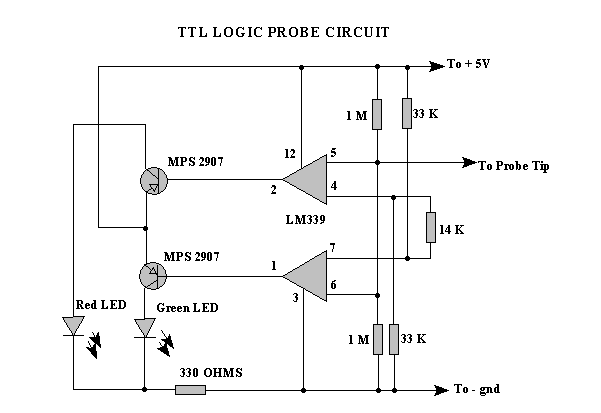
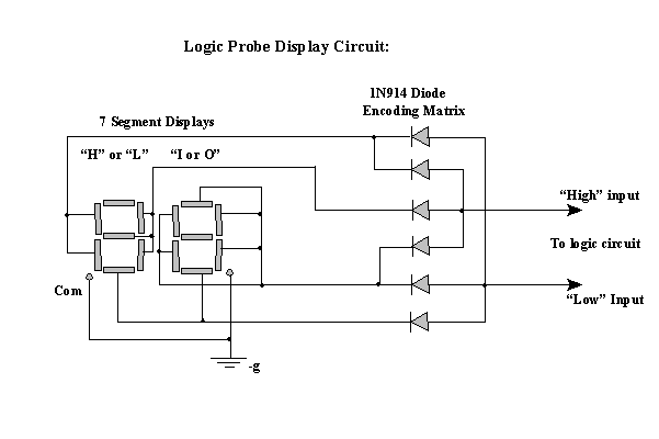
| A logic probe is a valuable tool to have included in ones assortment of test equipment. A basic logic tester is rather easy to design and build. They are especially needed in digital circuits for troubleshooting and design where an oscilloscope is not available. But for it to be useful one must understand what the flashing lights on the logic probe are showing in the circuit under test. Most logic probes have atleast two LEDs for displaying information and some use just one buzzer or speaker. The circuit below is in two parts, the first is the main circuit diagram. The second is the alphanumeric display composed of two 7- segment LEDs. |
 |
| To connect the 7 segment display circuit to the main logic circuit connect the point marked "High" in the display diagram with pin # 1 and connect the point marked "Low" to pin # 2 on the LM339. The main idea behind the 7 segment display is that it will display the words "HI" if the point under test is in the logic high state and it will display the word "LO" if the point is at a low state. By saying "LO" we mean the point is at the negative ground potential and "HI" for a positive potential. |