 |
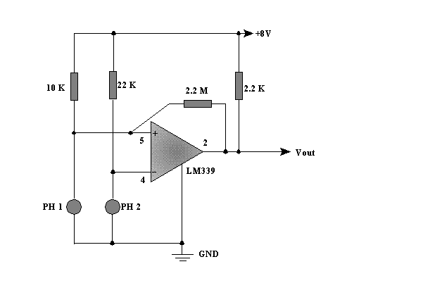
| Basic Photoresistor Schematic: |
 |
| Below is the basic photoresistor- comparator circuit used for Ostron eye design. This basic circuit is simply repeated for each of the other three comparators on the LM339 quad comparator IC. This was the original circuit I used for testing purposes and it performed as expected. V out for this circuit was about 0.17 Volts when "on" and equal to the positive supply rail of ~ 8 Volts when "off". The output voltage on pin 2 can be increased by simply replacing the 2.2 K resistor with a higher value. Voltage measurements were taken from common ground. I used a light with a dimmer control and variouse filters along with a digital multimeter to test the sensitivety and function of this circuit under many different conditions. One important aspect of this circuit I've found was that the photoresistors must have a change in resistance that is complementary to each other ,in otherwords they must be matched in both physical size and resistivity. For example those I've chosen all have a resistance of 1 megohm in total darkness and about 100 ohms in bright light, they all have a diameter of 0.2 inches. Though they all came from the same manufacturer and all were the same brand name, the resistance of some were completely different , reading only 100 K in total darkness and about 16 k in bright light. Out of the 20 I ordered only 6 had the same resistance and were suitable for this circuit. |
| Photoresistor-comparator schematic |