 |
| Comparator Pulse Generator |
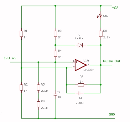
| Circuit Discription |
| R1 and R2 set the reference or trigger voltage of the comparator (LM339). R5 and R6 along with R3 and R4 form a voltage divider which sets the resting potential of C2. R7 and C1 provide hysteresis ( snap-action ) feedback to pin 4 which slightly shifts the reference voltage which improves comparator output response. R8 and the LED are used for monitoring the output. C2 charges through R3 and R4 and discharges through D2 and R4 Input pulses (I/V in) modulates the pulse generator. |
| Circuit is still in the design stage. |