A.Piermattei*, S. delle Canne*, L. Azario*, A. Russo*, A. Fidanzio*, R. Miceli*,
A. Soriani **, A. Orvieto** , M. Fantini **.
* Istituto di Fisica, Università Cattolica del S.Cuore, Roma, Italy
**Hitesys S.p.A., Aprilia (LT), Italy
Short title: Saturation loss for ion -chambers
PACS : 87.53 Hv
Abstract
The use of plane parallel ionization
chambers with electron beams with high dose per pulse entails dose uncertainties
due to the overestimation of the ion recombination factor, k, up to 20% if conventional
dosimetric protocols are used. In this work MD-55-2 radiochromic films have
been used as reference dosimeters to obtain absolute dose to water per pulse
![]() for
three Novac7 (Hitesys) electron beams of E0=5.8 MeV. However,
the beam calibration by MD-55-2 films is time consuming and the use of plane
parallel chambers is fundamental for periodic quality control procedure. Three
plane parallel chambers have been used and the general formula for the k determination
has been tested using the calibration doses,
for
three Novac7 (Hitesys) electron beams of E0=5.8 MeV. However,
the beam calibration by MD-55-2 films is time consuming and the use of plane
parallel chambers is fundamental for periodic quality control procedure. Three
plane parallel chambers have been used and the general formula for the k determination
has been tested using the calibration doses, ![]() .
In particular coherent ion recombination factors ksat(V0)
(with the ion chamber polarized at V0), that follow the Boag
theory, have been estimated at different dose per pulse values for the three
plane parallel ionization chambers. This means that at present any ion chamber
needs a specific ksat(V0) determination by using
a reference dosimeter that present an independent response to the dose rate.
An accurate determination of ksat(V0) using a reference
quality beam, can be used to determine the dose to water per pulse for electron
beams of different quality and geometrical configuration.
.
In particular coherent ion recombination factors ksat(V0)
(with the ion chamber polarized at V0), that follow the Boag
theory, have been estimated at different dose per pulse values for the three
plane parallel ionization chambers. This means that at present any ion chamber
needs a specific ksat(V0) determination by using
a reference dosimeter that present an independent response to the dose rate.
An accurate determination of ksat(V0) using a reference
quality beam, can be used to determine the dose to water per pulse for electron
beams of different quality and geometrical configuration.
The intraoperative radiation therapy (IORT) by using high dose values per pulse ranging from 3 cGy/pulse to 6 cGy/pulse is available by using the linac Novac7 (Hitesys) that supplies energy beams ranging from 4 MeV to 9 MeV.
Electron beam calibration is generally carried out by using plane parallel chambers that, however, present some complications in the accurate determination of the ion recombination factor when the dose rate per pulse is many times higher than the typical 0.01 cGy/pulse supplied by conventional clinical accelerators. Moreover, for these detectors there is a threshold polarizing voltage below which the chambers follow the Boag theory (Boag and Currant 1980). The existence of a deviation from the theory gives a limitation of the Boag two-voltage (TV) method (Boag and Currant 1980, Weinhous and Meli 1984). Indeed for dose per pulse values, in the range between 0.007 and 1.2 cGy/pulse, Burns and McEwen (1998) suggested, for a correct plane parallel chamber commissioning, the application of the graphical method, based on the extrapolation of the reciprocal signal, 1/M, as a function of the reciprocal voltage, 1/V.
As a result of this, GAF-Chromic films have been selected as reference dosimeters for the Novac7 electron beam calibrations. In particular, the radiochromic MD-55-2 films present high spatial resolution, low response dependence on the electron beam energy and independence for incidence beam angle. Moreover, the MD-55-2 films are made of water-equivalent material and can be used directly in water phantom. In this work the dose per pulse independence for MD-55-2 films has been tested by using chemical Fricke dosimeters.
Dose in water per pulse values at the reference point, for 5.8 MeV (Novac7) electron beams, were obtained by MD-55-2 films and compared with the dose in water per pulse determined by three plane parallel ionization chambers, Markus 23343, NACP-02 and Roos 34001. The results confirmed the overestimation of the ion-recombination factor, when the TV method was used for the three chambers.
Moreover, the dose in water per pulse, determined by MD-55-2 films, were used to obtain adequate values of saturation signals, MS, for the three chambers. The signals MV obtained at different polarizing voltage values, V, were used to obtain MS/MV ratios as a function of the 1/V. This way, the formula for the ion recombination factor, k, for pulsed radiation, which included the free-electron component (Boag et al. 1996, Hochhauser and Balk 1986), was tested for the three ionization chambers.
2.1 Novac7 linac electron beams
Novac7 (Figure 1) is a dedicated IORT linac robot developed to perform radiotherapy treatment during surgery to avoid moving the patient from the surgery room to the radiotherapy bunker. An articulated arm allows to vary the source-patient distance. The linac lays in a structure connected to the microwave source by a flexible waveguide. The pulse repetition frequency (prf) of 5 Hz has been optimized for the 4 ms electron pulses. However, the frequency can be changed from 1 Hz to 29 Hz to vary treatment times.
The linac Novac7 supplies electron beams of high values of dose per pulse ranging from 3 cGy/pulse to 6 cGy/pulse. The electron beams are collimated by 6 cm, 8 cm and 10 cm diameter perspex cylindrical collimators. Source-surface distances (SSD) equal to 80 cm and 100 cm can be used. Four nominal electron energy levels, 4 MeV, 5 MeV, 7 MeV and 9 MeV, allow performing treatments at different depths. In this work the electron beam, 7 MeV of nominal energy (an incident energy E0 = 5.8 MeV) was used. The ratio between the signal measured by an ionization chamber in water phantom and the pulse number was constant within 1%, in the range of 100 and 2000 pulses.
2.2 Radiochromic film
2.2.1. MD-55-2 film characteristics
MD-55-2 radiochromic films, ISP Technologies Inc. (LOT #38055), are supplied in sheets of 12.7x12.7 cm2 surface, made of a double-layer radiochromic sensor dispersion 30 mm in total thickness (AAPM 1998). The presence of the waterproof polyester bases make the film suitable to be irradiated directly in water. Due to the high spatial resolution (600 cycles / mm) (AAPM 1998) the MD-55-2 films can be used both for dose beam calibration as well as to obtain dose distributions (Piermattei et al. 1999).
The physical characteristics of these films are well reported in literature (AAPM 1998, Piermattei et al. 1998, Zhu et al. 1997). However, it is necessary to underline that the optical density (OD) depends on reading temperature (up to 1 % °C-1, at a reading temperature of about 14°C) and postirradiation reading time (up to 15% in the first 10 days and less then 1% per week in the following days) (Piermattei et al. 1998). To reduce uncertainties in dose determination, the films used for OD calibration and dose measurements were irradiated within a two hour interval time and the readout temperature was maintained constant between ± 0.25 °C. Due to the non-uniformity in the film emulsion layer, a ‘double irradiation technique’ (Zhu et al. 1997) was performed.
Software was developed to analyze the OD values of MD-55-2 film pieces 2x2 cm2 in size. OD readouts were carried out by using a 100 PeC microdensitometer mod. CCD100 (Photoelectron Corporation). The CCD100 incorporates a stable, uniform, monochromatic light source, obtained by an array of 60 gallium-aluminum arsenide LEDs, with a wavelength of 665 nm, closely matched to the absorption peak of the film maximum sensitivity (670 nm), and a high resolution camera for image acquisition. The acquired digital image is sent by a serial interface RS232 to an external computer to be analyzed. The distance between the CCD camera and the light box was fixed at 43 cm, to obtain an adequate pixel dimension, 0.3x0.4 mm2.
The OD interfilm precision or reproducibility (defined as the standard deviation of the mean OD values on separate film pieces, irradiated to the same dose) resulted lower than 1% (1s).
The energy independence test of the MD-55-2 films was reported in a recent work (Piermattei et al. 1999), where the films were calibrated in water by using an electron beam of incident energy E0 = 4.4 MeV, 5.6 MeV and a 7.2 MeV supplied by a Saturne 43 conventional linac. The OD values obtained by the same dose values, supplied by the above electron beams, were well in agreement within the interfilm precision.
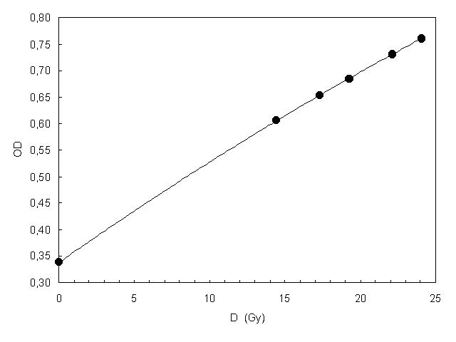
Figure 2 reports the OD values as a function of the absorbed dose to water for the E0=6.2 MeV electron beam supplied by the Saturne 43. The dose values were determined using the ENEA ESC/87 reference cylindrical ionization chamber. Figure 2 reports the film calibration curve obtained by fitting experimental values by a third degree polynomial curve, with a regression coefficient, R2=0.999. The OD=0.347 refers to the first irradiation at 10 Gy, while the second irradiation was carried out in the dose range between 14.6 Gy and 26.6 Gy.
2.2.2 MD-55-2 dose per pulse independence
The dose per pulse independence of
the MD-55-2 film (irradiated at doses equal to 20 Gy) was checked by using
chemical Fricke dosimeters that presented a radiation chemical yield independent
of the dose per pulse up to 10 Gy per pulse (ICRU 1982). Ferrous sulphate
in glass ampoules with inner dimensions equal to 7 mm in diameter and 20 mm
in length were irradiated in a water phantom at the reference depths (IAEA
1987) of two electron beams. The one supplied by a conventional linac Saturne
43 (6.2 MeV) with a prf = 200 Hz and the other supplied by the linac Novac7
(5.8 MeV and prf=5 Hz). Dose to water per pulse determined by the Fricke dosimeters,
![]() , were supplied by ENEA-INMRI
(Ente per le Nuove tecnologie, Energia Ambiente , Istituto Nazionale Metrologia
Radiazioni Ionizzanti), while the dose to water per pulse
, were supplied by ENEA-INMRI
(Ente per le Nuove tecnologie, Energia Ambiente , Istituto Nazionale Metrologia
Radiazioni Ionizzanti), while the dose to water per pulse ![]() at the same reference depths were determined by MD-55-2 Gaf-Chromic films
following the procedure reported in section 2.2.1.
at the same reference depths were determined by MD-55-2 Gaf-Chromic films
following the procedure reported in section 2.2.1.
Figure 3 shows the ![]() /
/
![]() ratios obtained at three
different dose per pulse values determined by Fricke dosimeters at 0.0390
cGy/pulse (6.2 MeV Saturne 43) and 2.89, 5.68 cGy/pulse (5.8 MeV Novac7).
The dose values obtained by MD-55-2 films for Novac7 electron beams resulted
independent of the dose per pulse within experimental errors.
ratios obtained at three
different dose per pulse values determined by Fricke dosimeters at 0.0390
cGy/pulse (6.2 MeV Saturne 43) and 2.89, 5.68 cGy/pulse (5.8 MeV Novac7).
The dose values obtained by MD-55-2 films for Novac7 electron beams resulted
independent of the dose per pulse within experimental errors.
When the ![]() were converted in average dose rate values (468 cGy/min, 866 cGy/min and 1704
cGy/min) the dose rate independence was in agreement with the data reported
in literature (AAPM 1998) for MD-55-2 films irradiated (by a 60Co
beam with dose rate values of 44, 2400 and 8000 cGy/min) at doses equal to
20 Gy.
were converted in average dose rate values (468 cGy/min, 866 cGy/min and 1704
cGy/min) the dose rate independence was in agreement with the data reported
in literature (AAPM 1998) for MD-55-2 films irradiated (by a 60Co
beam with dose rate values of 44, 2400 and 8000 cGy/min) at doses equal to
20 Gy.
2.2.3 MD-55-2 films used for Novac7 electron beam calibration
In this paper the MD-55-2 films were
used as reference dosimeters to obtain the absolute dose to water per pulse,
![]() , of three Novac7 beams
of E0 = 5.8 MeV, 6 cm (with SSD=80 cm), 8 cm (with SSD=80 cm) and
10 cm (with SSD=100 cm) in diameter.
, of three Novac7 beams
of E0 = 5.8 MeV, 6 cm (with SSD=80 cm), 8 cm (with SSD=80 cm) and
10 cm (with SSD=100 cm) in diameter.
For every beam, six pieces of films
(2x2 cm2 in size) were placed, two at a time, in water perpendicularly
to the beam central axis, at the reference depth, dref = 1.2 cm,
coincident with the depth of the beam maximum dose. A cylindrical ionization
chamber, positioned in water at the edge of the collimated beam, was used
to verify the beam stability during the film exposure. By means of the calibration
curve, reported in figure 2, the OD values were converted in dose to water
per pulse, ![]() .
.
2.2.4. Plane parallel ionization chambers
Three different plane parallel ionization chambers, a Markus mod. 23343 (PTW Freiburg), a Roos mod. 34001 (PTW Freiburg) and a NACP-02 (Scanditronix), connected to a Keithley mod. 35617 electrometer, were used to determine absolute dose values for the three Novac7 electron beams mentioned in section 2.2.3. The three chambers present a nominal electrode distance, d, equal to 2 mm, a polarity effect less than 0.5% (at low dose per pulse values) and water as recommended phantom material.
For the ionization chambers, the calibration factors, ND,P , in terms of absorbed dose in air were determined by comparison with the reference ionization chamber ENEA mod.ESC/87. Applying the Italian Protocol (AIFB 1988) (that follows the recommendation of the IAEA (1988)) a 21 MeV electron beam (20x20 cm2 in size at SSD=100 cm), supplied by the conventional linac Saturne 43 (with a prf=100 Hz) was selected for the comparison. Table I reports the nominal sensitive volumes, the recommended (by manufacturer) polarizing voltage values, V1, together with the calibration factor values, ND,P. These last values were calculated by averaging the calibration factors obtained with polarizing voltage, V, ranging between 50 V and the threshold voltage, V0 , as determined in the result section. The percentage standard deviations for the ND,P values (reported in table I), were coincident with the reproducibility of the ionization chamber signal.
|
Ionization chamber Model |
Nominal sensitive volume (cm3)
|
V1 (V) |
ND, P
(108 Gy/C) |
|
Markus mod.23343
|
0.055 |
300 |
5.043 ± 0.015 |
|
NACP-02
|
0.160 |
200 |
1.360 ± 0.005 |
|
Roos mod. 34001
|
0.350 |
100 |
0.781 ± 0.003 |
Table I - Nominal sensitive volumes, recommended polarizing voltage values, V1, and calibration factors, ND,P .
For the three Novac7 electron beams
obtained by collimators 6, 8, and 10 cm in diameter, the ion recombination
factors, ksat (AIFB 1988), for the three chambers, were
determined using the two-voltage (TV) method (Weinhous and Meli 1984). The
ksat values were used to determine the absorbed dose to
water per pulse, ![]() , at
the reference point, dref = 1.2 cm following the AIFB 1988 protocol.
As reported in literature, for high dose per pulse values, the ksat
factors could be overestimated due both to the unattached electrons to oxygen
molecules of the gas (Boag 1950, Hochhauser and Balk 1986, Boag et al. 1996,
Burns and Burns 1993) as well as to the chamber response dependence on the
polarizing voltage (Buns and McEwen 1998, Nisbet and Thwaites 1998). Indeed
the use of polarizing voltage values above threshold voltage values, V0,
entails a limitation of the Boag two-voltage analysis. To investigate these
phenomena, dose to water per pulse values, dw(V)
, non correct for ion recombination (assuming ksat=1) were
determined using the signals MV obtained with different
polarizing voltages, V, and the ND,P calibration factors
reported in table I (AIFB 1988). Dose values
, at
the reference point, dref = 1.2 cm following the AIFB 1988 protocol.
As reported in literature, for high dose per pulse values, the ksat
factors could be overestimated due both to the unattached electrons to oxygen
molecules of the gas (Boag 1950, Hochhauser and Balk 1986, Boag et al. 1996,
Burns and Burns 1993) as well as to the chamber response dependence on the
polarizing voltage (Buns and McEwen 1998, Nisbet and Thwaites 1998). Indeed
the use of polarizing voltage values above threshold voltage values, V0,
entails a limitation of the Boag two-voltage analysis. To investigate these
phenomena, dose to water per pulse values, dw(V)
, non correct for ion recombination (assuming ksat=1) were
determined using the signals MV obtained with different
polarizing voltages, V, and the ND,P calibration factors
reported in table I (AIFB 1988). Dose values ![]() and dw(V) , were determined from
the mean value of the signals (at standard temperature and pressure) obtained
inverting the polarization. The dw(V) values
were compared with
and dw(V) , were determined from
the mean value of the signals (at standard temperature and pressure) obtained
inverting the polarization. The dw(V) values
were compared with ![]() and
and
![]() values obtained for the
three electron beams. As for
values obtained for the
three electron beams. As for ![]() measurements, the dose per pulse obtained by ionization chambers were carried
out testing the beam stability.
measurements, the dose per pulse obtained by ionization chambers were carried
out testing the beam stability.
3.1 Threshold polarizing voltage values for plane parallel ionization chambers.
Following the Boag theory (Boag and Currant 1980, Burns and McEwen 1998) the ion recombination factor, k, for the three plane parallel ionization chambers at low dose per pulse values can be approximated by


where u = C/V, and C is
a constant given by the product of m
(a constant which depends on gas of the cavity); r (the charge
density of positive ions liberated per pulse) and ![]() (the
square of the chamber electrode distance) (Boag and Current 1980).
(the
square of the chamber electrode distance) (Boag and Current 1980).
Following Burns and McEwen (1998) suggestions the best estimation of the saturation signals, MS , for a 21 MeV electron beam (Saturne 43) was obtained using the MV signals (at standard temperature, pressure and constant number of monitor units) that better follow the linear approximation of 1/MV versus 1/V. Figure 4 shows the ratios MS/MV obtained for the three ionization chambers as a function of 1/V for constant monitor units. The solid line is the linear fit of the ratios with a polarizing voltage below a threshold value, V0, where equation 1 is satisfied. In this way the values, V0, for the three ionization chambers were determined and reported in table II. The value V0=140 V less than the V1=200 V for the NACP-02 ion-chamber is in agreement with the result obtained by Burns and McEwen (1998).
By equation (1) and the data reported in figure 4, the parameters C were determined for the three ionization chambers. The consistence of these values was verified determining the effective plate separation deff values of the ionization chambers, that are proportional to the ratios between the C values and the absorbed dose to air per pulse, Dair,p , in the collecting volume of the ionization chambers. Indeed if the charge density, r, is determined by:
where rair is the air density , W is the average energy required to create an electron-ion pair in air, e is the electronic charge and Dair,p is determined by the product of the saturation signal per pulse, MS,p , and ND,P :
![]()

the deff can be determined by:
Using the values µ=3.02 1010 V m C-1 (ICRU 1982), (Wair/e)=33.97 JC-1 (CCEMRI 1985) and rair=1.205 Kg m-3 (at standard temperature and pressure), the deff value (this is not necessarily the actual plate separations) for each ion chamber was within 10% in agreement with the nominal plate separation, d, reported by the chamber manufacturers. The deff values and the C/Dair,p ratios, obtained for the three ionization chambers, are reported in table II.
|
Ion-chamber model
|
V0 (V) |
C/Dair,p (V /cGy) |
deff (mm) |
|
Markus - 23343 |
160 |
51.3 ± 0.5 |
2.2 |
|
NACP-02 |
140 |
51.7 ± 0.5 |
2.2 |
|
Roos-34001 |
100 |
35.0 ± 0.4 |
1.8 |
Table II – Threshold voltage values, V0, C/Dair,p ratios and effective plate separation, deff, determined for the three plane parallel ionization chambers. The uncertainties for C/Dair,p ratios were estimated as propagation of the MS,p (0.7%), ND,P (0.5%) and C (0.5%) uncertainties.
3.2 Absorbed dose to water for Novac7 electron beams.
The absorbed dose to water per pulse
(at dref = 1.2 cm), ![]() ,
of the three Novac7 electron beams were determined and reported in table III.
The dose uncertainty of 2.7% (1s ) was estimated
combining in quadrature the uncertainty of 2.5% (1s
) due to the MD-55-2 film calibration and the uncertainty of 1% (1s
) due to OD interfilm reproducibility.
,
of the three Novac7 electron beams were determined and reported in table III.
The dose uncertainty of 2.7% (1s ) was estimated
combining in quadrature the uncertainty of 2.5% (1s
) due to the MD-55-2 film calibration and the uncertainty of 1% (1s
) due to OD interfilm reproducibility.
The dose per pulse values, ![]() ,
were determined and reported in table III. The dose uncertainty for
,
were determined and reported in table III. The dose uncertainty for
![]() 2% (1s
) were determined following the protocol AIFB (1988). The percentage polarity
effect resulted lower than 1% for both Roos 34001 and NACP-02 ionization chambers
while for the Markus chamber it resulted equal to 7%. This last value resulted
greater than 4% observed by Nisbet and Thwaites (1998) for conventional dose
per pulse values.
2% (1s
) were determined following the protocol AIFB (1988). The percentage polarity
effect resulted lower than 1% for both Roos 34001 and NACP-02 ionization chambers
while for the Markus chamber it resulted equal to 7%. This last value resulted
greater than 4% observed by Nisbet and Thwaites (1998) for conventional dose
per pulse values.
|
Beam diameter (cm) |
|||
|
10 |
8 |
6 |
|
|
|
3.03 |
5.30 |
6.20 |
|
|
3.62 |
6.09 |
7.43 |
|
|
3.55 |
5.94 |
6.84 |
|
|
3.55 |
5.69 |
6.43 |
Table
III – Absorbed doses to water obtained using MD-55-2 films, ![]() ,
and using plane parallel ionization chambers (Markus-23343, NACP-02 and Roos-34001)
,
and using plane parallel ionization chambers (Markus-23343, NACP-02 and Roos-34001)
![]() .
.
Figure 5 reports, for the three ionization
chambers irradiated with the electron beam 10 cm in diameter, the dw(V)
values and two asymptotic lines, the dashed line represents the absorbed dose
per pulse, ![]() ,
value, while the dotted line represents the dose per pulse
,
value, while the dotted line represents the dose per pulse ![]() value. A qualitative analysis of the results, reported in figure 5, suggests
that the
value. A qualitative analysis of the results, reported in figure 5, suggests
that the ![]() values cannot be considered adequate asymptotic saturation dose values for the
three ionization chambers. Moreover the percentage variation of the
values cannot be considered adequate asymptotic saturation dose values for the
three ionization chambers. Moreover the percentage variation of the ![]() values, reported in table III, is within ± 7%
and these values are up to 20% higher than the
values, reported in table III, is within ± 7%
and these values are up to 20% higher than the ![]() values.
values.
Figure 5 shows that at high dose per pulse values the collection efficiency, f, at the polarizing voltage values here used, is lower than 0.95. This means that the saturation signal MS cannot be estimated by a linear extrapolation of 1/M against 1/V as used by Burns and McEwen (1998) for low dose per pulse values. Moreover, the effect of free electron collection on the evaluation of the ion recombination factor has to be considered. For these reasons the general formula for the ion recombination factor, k=1/f, (Hochhauser and Balk 1986, Boag et al. 1996) has been used:

where:
p is the free-electron fraction, that is a function of the polarizing voltage, p(V); u=C/V is the same parameter reported in equation (1).
By using the dose to water per pulse
![]() , the saturation signals
per pulse, MS, (at standard temperature and pressure) for
the three plane parallel chambers were estimated as:
, the saturation signals
per pulse, MS, (at standard temperature and pressure) for
the three plane parallel chambers were estimated as:

where ![]() is the ratio of the effective mass collision stopping power of water to that
of air, (AIFB 1988) and the ND,P is the chamber calibration
factor (table I). The MS uncertainty equal to 4% (1s
) was estimated combining in quadrature the uncertainties of the parameters
reported in equation (4).
is the ratio of the effective mass collision stopping power of water to that
of air, (AIFB 1988) and the ND,P is the chamber calibration
factor (table I). The MS uncertainty equal to 4% (1s
) was estimated combining in quadrature the uncertainties of the parameters
reported in equation (4).
Therefore, the equation (3) can be rewritten as:

By the MV signals, determined at a different polarizing voltages, V, the ratios MS/MV were used in equation (5). A software iterative procedure that minimized the differences between the first and second member of equation (5) was used to optimize the choice of the C and p(V) values. The procedure included two constraints:
The p(V) values for the three plane parallel ionization chambers (with nominal plate separation d=2 mm) ranged between 0.05 and 0.15 at V=100 V while at V=150 V p(V) values ranged between 0.10 and 0.20. These results were coherent with those determined by Boag (1987) and Boag et al. (1996) for plane parallel ionization chambers with electrodes distances between 1 mm and 6 mm.
The C and p(V) values, determined by the iterative procedure, were used to implement equation (3) for the three plane parallel chambers. Figure 6 reports the MS/MV ratios obtained at 5.30 cGy/pulse fitted by equation (3) as a function of the parameter u. Up to the threshold polarizing voltage V0 values, (determined at conventional dose per pulse values), the differences between MS/MV ratios and k values (equation 3) resulted within 3 % for Roos and NACP-02 chambers and 5% for Markus.
The mean C/Dair,p values obtained for the three ionization chambers at conventional and high dose per pulse values resulted 50.6 ± 2.0 ; 53.2 ± 0.5 and 35.5 ± 0.2 (V/cGy) for Markus, NACP and Roos ionization chambers, respectively.
Figure 7 reports, for the three ion chambers,
the dw(V0) values as a function of ![]() (obtained at three high dose per pulse values) fitted by a second degree polynomial
curve. The differences between the curve and the bisector line are representative
of the ion recombination factor at V0, ksat(V0)
that can be obtained by:
(obtained at three high dose per pulse values) fitted by a second degree polynomial
curve. The differences between the curve and the bisector line are representative
of the ion recombination factor at V0, ksat(V0)
that can be obtained by:


In this work, MD-55-2 radiochromic films have been used as reference dosimeters to obtain the dose calibration of three Novac7 electron beams (E0=5.8 MeV) of high dose per pulse used for the IORT technique. For the MD-55-2 films the OD independence of dose per pulse has been tested by using Fricke chemical dosimeters. The high spatial resolution and the possible use of the film in water phantom makes the radiochromic film attractive for absolute and relative dosimetry of high dose per pulse radiation beams of different configuration and dimension. The dosimetric uncertainty was estimated of about 2.7 % (1s ).
However, the electron beam calibration by radiochromic films results time consuming and this makes the use of such dosimeters unsuitable for periodic quality control procedures, where the use of a plane parallel ionization chamber is fundamental (IAEA 1997). Nevertheless, the use of ionization chambers at high dose per pulse values, entails dose uncertainties due to: a) the overestimation of the ion recombination factor, k , up to 20% if conventional dosimetric protocols are used; b) the percent polarity effect can result greater than 1%. For the dose per pulse values here examined the percentage polarity effect resulted lower than 1% for both Roos 34001 and NACP-02 ionization chambers while for the Markus chamber it reached 7%. It is important to remember that a high polarity effect may increase during the lifetime of the ion chamber (IAEA 1997), this means that it is important to check the polarity effect of the chamber, regularly.
For any newly commissioned chamber, a plot of MS/MV ratios against 1/V (figure 4) is recommended. In this work, the general formula for k determination (equation (3)) was used to fit MS/MV ratios and the existence of a threshold voltage value, V0, at high dose per pulse values seems to be also confirmed.
An ion recombination factor ksat(V0)
coherent with the Boag theory has been estimated at three different dose per
pulse values as ratio of the dose to water per pulse measured by GAF-Chromic
film, ![]() , and the uncorrected
dose to water dw(V0) (equation 6). However,
it is important to observe that the results reported in figure 7 for the three
ionization chambers are only indicative for other ionization chambers of the
same model. Indeed, as reported by Burns and McEwen [1998], for an NACP-02 ion
chamber, differences in the parallel plate separation of 0.16 mm entails differences
in the ion recombination factor up to 8%. This means that, at present, any chamber
needs a specific ksat(V0) vs dw(V0)
calibration by using a reference dosimeter that presents an independent response
to the dose rate. However, it is important to underline that an accurate determination
of ksat(V0) at a reference quality beam, can be
used to determine the dose to water per pulse for electron beams of different
quality (Burns and Burns 1993) and different geometrical configuration.
, and the uncorrected
dose to water dw(V0) (equation 6). However,
it is important to observe that the results reported in figure 7 for the three
ionization chambers are only indicative for other ionization chambers of the
same model. Indeed, as reported by Burns and McEwen [1998], for an NACP-02 ion
chamber, differences in the parallel plate separation of 0.16 mm entails differences
in the ion recombination factor up to 8%. This means that, at present, any chamber
needs a specific ksat(V0) vs dw(V0)
calibration by using a reference dosimeter that presents an independent response
to the dose rate. However, it is important to underline that an accurate determination
of ksat(V0) at a reference quality beam, can be
used to determine the dose to water per pulse for electron beams of different
quality (Burns and Burns 1993) and different geometrical configuration.
References
AAPM 1998 (American Association of Physicists in Medicine) Radiochromic film dosimetry: Recommendations of AAPM Radiation Therapy Committee Task Group 55. Med. Phys. 25(11), 2093-2115.
AIFB 1988 (Associazione Italiana di Fisica Biomedica) Protocollo per la dosimetria di base nella radioterapia con fasci di fotoni ed elettroni con Emax fra 1 e 40 MeV. Notiziario della A.I.F.B. VI(2).
Boag J W 1950 Ionization measurements at very high intensities: Pulsed radiation beams. Brit. J. Radiol. 23; 601-611.
Boag J W 1987 Ionization chambers. In dosimetry of Ionization Radiation, Vol 2; 169-239 (K.R. Kase, B Bjarngard , F.H. Attix , eds), Academic Press, New York.
Boag J W and Currant J 1980 Current collection and ionic recombination in small cylindrical ionization chambers exposed to pulsed radiation. Brit. J. Radiol. 53; 471-478.
Boag J W , Hochhauser E , Balk O A 1996 The effect of free-electron collection on the recombination correction to ionization measurements of pulsed radiation. Phys. Med. Biol. 41, 885-897.
Burns J E and Burns D T 1993 Comments on "Ion recombination correction for plane-parallel and thimble chambers in electron and photon radiation", Phys. Med. Biol. 38, 1986-88.
Burns D T and McEwen M R 1998 Ion recombination for the NACP parallel-plate chamber in a pulsed electron beam. Phys. Med. Biol. 43, 2033-2045.
CCEMRI 1985 (Comitè Consultatif pour les Etalons de Mesure des Rayonnements Ionisants) Report of the 8th meeting of Section I to the Comité Intertnational des Poids et Mesures Comité Consultatif pour les Etalons de Mesure des Rayonnements Ionisants, Rapport de la 11e session ; R150-R162.
Hochhauser E and Balk OA 1986 The influence of unattached electrons on the collection efficiency of ionisation chambers for the measurements of radiation pulses of high dose rate. Phys. Med. Biol. 31, 223-233.
IAEA 1987 (International Atomic Energy Agency) Absorbed Dose Determination in Photon and Electron Beams. An International code of practice for dosimetry TRS No. 277, Vienna 1987.
IAEA 1997 (International Atomic Energy Agency) The use of plane parallel ionization chambers in high energy electron and photon beams - An International Code of Practice for Dosimetry’. Vienna 1997.
ICRU 1982 (International Commission on Radiation Units and Measuraments) Report No. 34, The dosimetry of pulsed radiation.
Nisbet A and Thwaites D I 1998 Polarity and ion recombination correction factors for ionization chambers employed in electron beam dosimetry. Phys. Med. Biol. 43; 435- 443.
Piermattei A , Azario L , Fidanzio A , Arcovito G 1998 Quasi water-equivalent detectors for photon beams that present lateral electron disequilibrium. Phys. Med. 14(1) , 9-17.
Piermattei A , Delle Canne S , Azario L , Fidanzio A , Soriani A , Orvieto A , Fantini M 1999 , Linac Novac7 electron beam calibration using GAF-Chromic film. Phys. Med. 15(4) In press.
Weinhous M S and Meli J A 1984 Determining Pion the correction factor for recombination losses in a ionization chamber. Med. Phys. 11(6) , 846-849.
Zhu Y , Kirov A S , Mishra V , Meigooni A S , Williamson J F 1997 Quantitative evaluation of radiochromic film response for two-dimensional dosimetry. Med. Phys. 1997 24(2) , 223-231.
Acknowledgements
We gratefully acknowledge D. Di Nucci, P. Di Nicola for their technical assistance. This work was supplied by grants from MURST (Ministero dell’Università e della Ricerca Scientifica e Tecnologica).
FIGURES and CAPTIONS
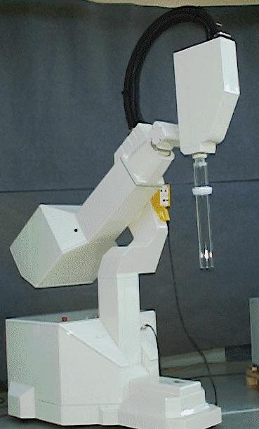
Figure 1 – Dedicated IORT linac robot developed to perform radiotherapy treatment during surgery. The external dimensions are 2.55 m in height, 2.3 m in length, 1 m in width and the weight is 600 Kg.
Figure
2 – MD-55-2 film calibration in terms of optical density OD (![]() )
vs absorbed dose to water, by using an electron beam of E0 = 6.2
MeV supplied by a conventional linac (Saturne 43). The OD=0.347 refers to the
first irradiation at 10 Gy. The fit is obtained by using a third degree polynomial
curve. The symbol dimension is representative of OD precision.
)
vs absorbed dose to water, by using an electron beam of E0 = 6.2
MeV supplied by a conventional linac (Saturne 43). The OD=0.347 refers to the
first irradiation at 10 Gy. The fit is obtained by using a third degree polynomial
curve. The symbol dimension is representative of OD precision.
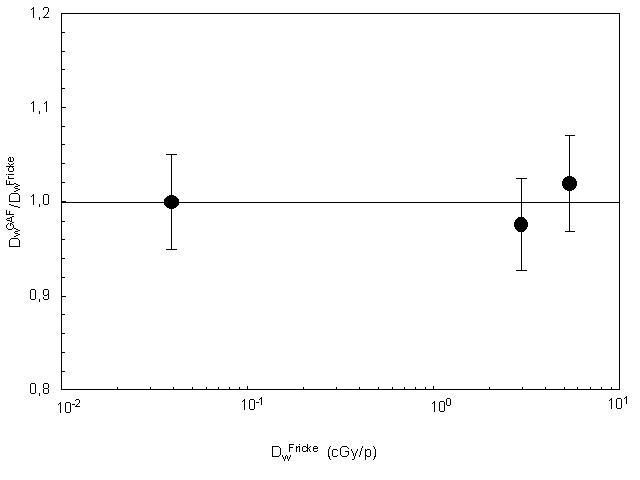
Figure
3 – ![]() /
/![]() ratios (
ratios (![]() ) at three different
dose per pulse values: 0.0390 cGy/pulse, 2.96 cGy/pulse and 5.38 cGy/pulse,
are reported. The bars are representative of the uncertainties determined as
propagation of dose uncertainties (2.7%, 1s)
for
) at three different
dose per pulse values: 0.0390 cGy/pulse, 2.96 cGy/pulse and 5.38 cGy/pulse,
are reported. The bars are representative of the uncertainties determined as
propagation of dose uncertainties (2.7%, 1s)
for ![]() and (1.4%, 1s)
for
and (1.4%, 1s)
for ![]() .
.


Figure
4 – MS/MV ratios (![]() )
as a function of 1/V obtained for the three ionization chambers, (a) Markus.
Mod. 23334, (b) NACP-02, (c) Roos mod. 34001, irradiated by a 21 MeV (Saturne
43) electron beam. The solid line is the linear fit of the ratios with a polarizing
voltage below the value V0 (
)
as a function of 1/V obtained for the three ionization chambers, (a) Markus.
Mod. 23334, (b) NACP-02, (c) Roos mod. 34001, irradiated by a 21 MeV (Saturne
43) electron beam. The solid line is the linear fit of the ratios with a polarizing
voltage below the value V0 (![]() ).
).


Figure
5 – The dw(V) values (![]() )
and asymptotic lines are reported. The dotted lines represent the value
)
and asymptotic lines are reported. The dotted lines represent the value ![]() =3.03
cGy/pulse while the dashed lines represent the
=3.03
cGy/pulse while the dashed lines represent the ![]() values obtained by the Markus mod. 23334 (a), NACP-02 (b) and Roos mod. 34001
(c). The result were obtained with the Novac7 electron beam, 10 cm in diameter.
values obtained by the Markus mod. 23334 (a), NACP-02 (b) and Roos mod. 34001
(c). The result were obtained with the Novac7 electron beam, 10 cm in diameter.


Figure
6 – MS/MV ratios (![]() )
at 5.30 cGy/pulse obtained for the three ionization chambers: Markus mod. 23334
(a), NACP-02 (b), Roos mod. 34001 (c) as a function of parameter u. The continuous
curves (equation 3) represent k vs u. The closed symbols (
)
at 5.30 cGy/pulse obtained for the three ionization chambers: Markus mod. 23334
(a), NACP-02 (b), Roos mod. 34001 (c) as a function of parameter u. The continuous
curves (equation 3) represent k vs u. The closed symbols (![]() )
indicate the results obtained at V0.
)
indicate the results obtained at V0.


Figure
7 – dw(V0) values as a function of
![]() obtained by the Markus
mod. 23334 (a), NACP-02 (b), Roos mod. 34001 (c) ionization chambers irradiated
at 3.03, 5.30 and 6.20 cGy/pulse. The data are fitted by second degree polynomial
curves.
obtained by the Markus
mod. 23334 (a), NACP-02 (b), Roos mod. 34001 (c) ionization chambers irradiated
at 3.03, 5.30 and 6.20 cGy/pulse. The data are fitted by second degree polynomial
curves.