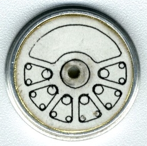
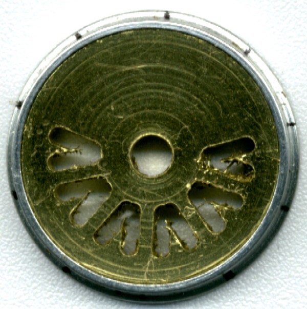
Paper pattern from IntelliCad 2000 drawing glued to driver.
18 holes drilled and openings cut out with jeweler's saw.
Spokes
I had quite a problem making nice even spokes. When I was still using the Dremel drill press I simply drilled out three holes per opening & cut out the triangle with a jeweler's saw. I got varying results with this method & each driver took a long time to cut out. I attempted to use a small mill bit in the Dremel, but the slightest chatter would completely ruin the opening as the bit bounced from side to side. The Dremel bearings are just too sloppy to do a good job milling.
Paper pattern from IntelliCad 2000 drawing glued to driver.
18 holes drilled and openings cut out with jeweler's saw.
After I got the Taig I made a milling jig to hold the driver centers. The jig is a 1/4" thick aluminum plate with a 1/8" brass rod pressed into it. The rod extends 5/16" out from the plate and I taped a CAD drawing of the ten spoke centerlines over it.
I align the jig by loosely bolting it to the Taig's milling attachment, and placing the rod into a 1/8" collet mounted on the lathe's headstock. After tightening the jig up I slide the jig back out and put a 3/32" milling bit (with a 1/8" shank) into the collet.
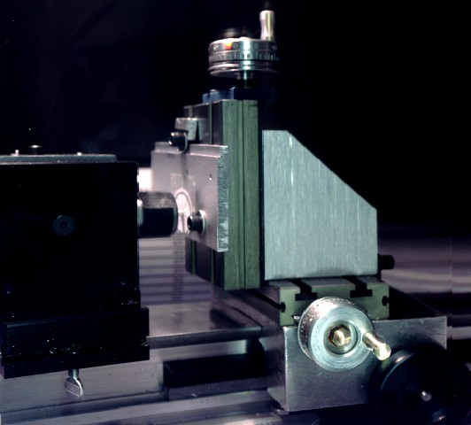
I move the milling attachment and the jig down vertically and move the cross slide horizontally to one of the inner starting corners of an opening. I mill one slot from the inside corner downwards towards the rim, and then move the cross slide horizontally to the next opening. I mill that slot and then rotate the driver center 36 degrees. (repeat as necessary for the number of spokes desired) I end up with very uniform spokes this way & it actually takes less time than marking out & drilling 18 separate holes.
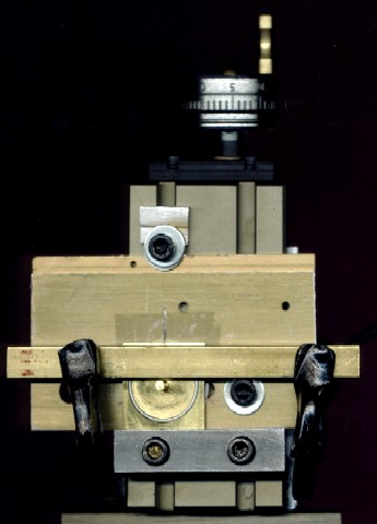
Clamping driver to prevent movement is essential! I made a square brass holding
piece to fit over driver rim and then clamp the driver center, rim, and holder
to the jig with a brass bar & two C-clamps.
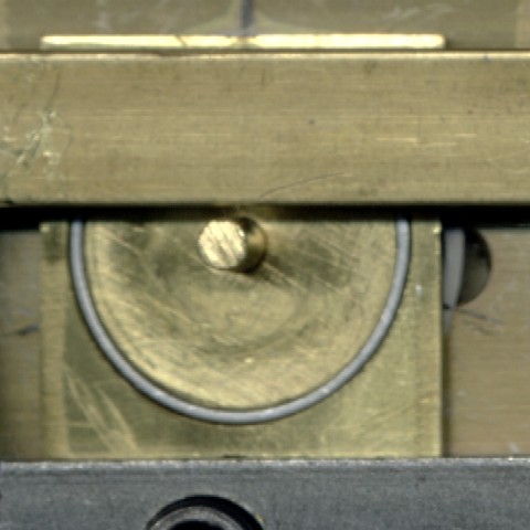
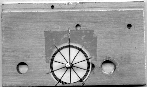
Clamped driver assembly ready for milling
After cutting one vertical slot on each side of a spoke the driver is rotated
36 degrees.
Black dots on outside of rim are aligned with the spoke centerlines on the CAD
drawing taped to the jig.
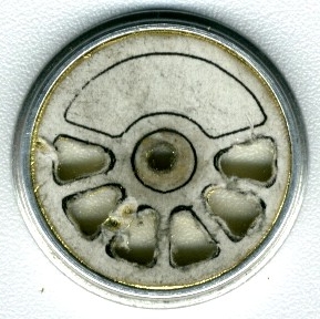
Openings are finished off using a jeweler's saw and files.
You are visitor number
Last update Jan 3, 2002

