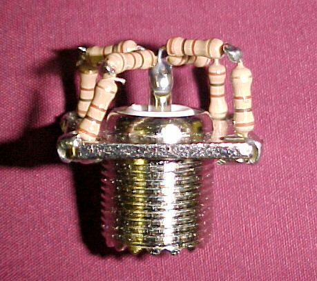
Construction is simple. Solder two resistors together in an "L" shape. Do this three more times with the other resistors. Solder one end of the resistor pair to one of the holes in the jack, and the other end to the center conductor of the jack. Do it for all four resistor pairs so that you have 200 Ohms in parallel four times.
The dummy load can be connected to a radio with a short coax jumper or a double-male PL-259 plug.
If 1/2-watt resistors are used, the power dissapation should be at 4 watts. However, it is possible to transmit up to 10 watts into the dummy load for very short lengths of time. 1/4-watt resistors can be used, but the maximum power dissapation would be at 2 watts.