L=234/F
L is the length in feet for each leg. F is the frequency the antenna is to be used on. For example, if you want a dipole to use on 40 meters CW, you take 234 divided by 7.030 for a length of approximately 33.3 feet. This is for each leg, giving a total length of around 66 1/2 feet. The antenna will probably need to be trimmed by checking the VSWR with an SWR meter or antenna analyzer. Just trim a few inches off at a time, cutting the same length of each end.
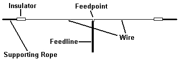
The dipole is fed with either twinlead feedline or coaxial cable. 50 Ohm coax is most common for halfwave dipoles as the halfwave design will provide a 50 Ohm impedance at the feedpoint. Twinlead is also used since it has lower loss than coax, but the impedance of twinlead is usually around 300 or 450 Ohms. A balun or matching network will be needed to match the high impedance to the 50 Ohm impedance of a ham transceiver or shortwave receiver.
It is easy to construct a feedpoint to use coaxial cable to a dipole. The following diagram shows how I constructed mine:
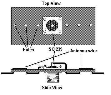
I drilled three holes on both sides of the SO-239 to thread the wire through, alternating them for strain relief. I soldered one wire to the center conductor of the SO-239. I attached a round terminal lug to the other wire and connected it to one of the nuts holding the SO-239 to the plastic base. I then coated the entire back side of the SO-239 with epoxy to weatherproof the connection.
For best results, a dipole should be mounted at least 1/4 wavelength above the ground. In the case of an 80 meter dipole, this probably won't be too feasible. The 1/4 wavelength above ground will provide you with a bidirectional antenna pattern with strong lobes broadside to the antenna and nulls at the ends. If the antenna is less than 1/4 wavelength above ground, it will still work fine, of course, but the pattern will have many additional lobes and will be less directional. More of the signal transmitted from the antenna will tend to go higher above the horizon. This, however, isn't a bad thing if you want to use the antenna for NVIS, or Near-Vertical Incidental Skywave, which is a method of communicating short distances by beaming a signal nearly straight up and having it bounce down off the ionosphere.
One last thing to note is that a dipole cut for the 80 meter ham band can, with a tuner, operate on the 40, 20, and 10 meter ham bands with good results. Depending on the tuner, it will probably be able to be tuned up on the other bands as well, but won't be as efficient as on the harmonic bands. If an antenna tuner isn't available or you'd rather not use one, a multiband dipole can be constructed by adding additional elements for different bands.