Wideband Scanner Antenna
This antenna is a simple double bowtie biconical dipole design.  It was designed as a broadband scanner antenna resonant on the 2 meter ham band.  The biconical design gives it broadband characteristics, and the double bowtie design makes it omnidirectional.  The central supporting mast consists of a wooden broom handle, and the elements are made from wire coat hangers. 
The length of the wire elements is found by using the standard L=234/F formula for each leg of the dipole, where L=length in feet and F=Frequency in MHZ.  This will be the formula to determine the entire length of the wire.  When I built this antenna I miscalculated and made the length of the wire roughly 19 inches from the feedpoint to the end of each leg of the antenna, not taking into consideration the length of wire reaching from the outer edge of the cone to the mast.  So the antenna I built, which was supposed to be resonant around 145 MHZ, was actually resonant with a 1.5:1 or less VSWR from around 54-108 MHZ, with the flattest SWR at the lower edge of the FM broadcast band.  The total length of the wire elements, before being bent, should rely on the L=234/F formula.  However, the antenna did turn out to be fairly broadbanded having an acceptable SWR over the 2 meter ham band and on up to around 175 MHZ, the upper limit of my antenna analyzer.  It also hears UHF signals quite well.  It should also be noted that since this antenna is a biconical design, use the lowest frequency you want to use the antenna on for F in the formula.

The bend in the elements isn't critical, but mainly depends on how fat you want the end of each cone.  The fatter the cone, the wider the bandwidth, however you will trade some gain for bandwidth when you do this.  I suggest experimenting a bit.  Generally, though, having the horizontal part of the element a little less than half as long as the vertical part of each element should work well.  One thing that is important is to make sure all elements are the same length & shape.  Cut & bend the first element, then use it as a guide to bend the rest of the elements. 

To connect the elements to the mast, I drilled holes for the wires and then fixed them to the mast with epoxy.  The antenna is fed in the center like a normal dipole, either using a connecter such as a female BNC, SO-239, or connecting the cable directly to the elements.  It should be noted that the elements for each side of the dipole must all be connected together at the feedpoint.  The far end does not need to be connected.  Even though I showed the coax connections one way in the diagram below, it does not matter which side of the coax is connected to the upper or lower side of the antenna.
Once you have the antenna put together, you will probably want to paint it.  It is recommended to do so if you use a wooden mast or bare wire.  I suggest using a flat primer grey paint as it makes antennas harder to see against the sky, whether it is a blue sky or grey overcast. 

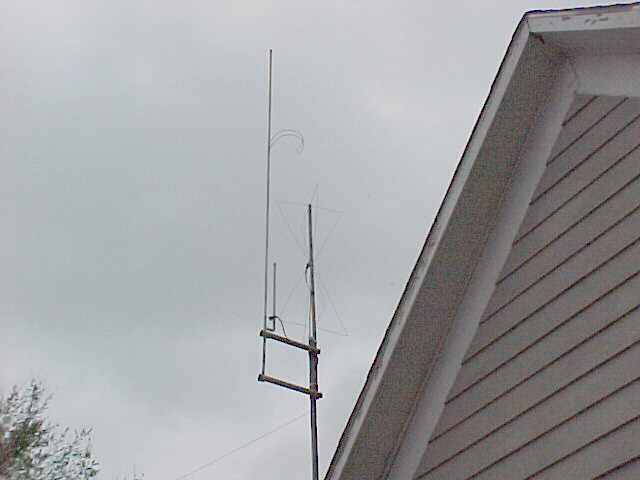
A pic of this antenna in action can be seen
here

In 2003 I took this antenna down after a couple years of service and found that the weather had deteriorated the antenna to the point that it wasn't worth fixing.  Even though I had used several coats of paint on the wooden broom handle, it still rotted & warped from the sun, rain, and ice.  If I rebuild this antenna I will definitely use a fiberglass or PVC mast.  I wouldn't recommend using a wooden mast unless it was very well treated against weathering.  PVC or fiberglass will stand up to the weather much better.
HomebrewingHome
Hosted by www.Geocities.ws

1