It is now time to turn our attention from the applications and social aspects of networking to the technical issues involved in network design. There is no generally accepted taxonomy into which all networks fit, but two dimensions stand out as important: transmission technology and scale. We will now examine each of these in turn.
Broadly speaking, there are two types of transmission technology:
1) Broadcast networks.
2) Point-to-point networks.
Broadcast networks have a single communication channel that is shared by all the machines on the network. Short messages, called packets in certain contexts, sent by any machine are received by all the others. An address field within the packet specifies for whom it is intended. Upon receiving a packet, a machine checks the address field. If the packet is intended for itself, it processes the packet; if the packet is intended for some other machine, it is just ignored.
As an analogy, consider someone standing at the end of a corridor with many rooms off it and shouting "Watson, come here. I want you." Although the packet may actually be received (heard) by many people, only Watson responds. The others just ignore it.
Broadcast systems generally also allow the possibility of addressing a packet to all destinations by using a special code in the address field. When a packet with this code is transmitted, it is received and processed by every machine on the network. This mode of operation is called broadcasting. Some broadcast systems also support transmission to a subset of the machines, something known as multicasting.
In contrast, point-to-point networks consist of many connections between individual pair of machines. To go from the source to the destination, a packet on this type of network may have to first visit one or more intermediate machines. Often multiple routes, of different lengths are possible, so routing algorithms play an important role in point-to-point networks. As a general rule, smaller, geographically localized networks tend to use broadcasting, whereas larger networks usually are point-to-point.
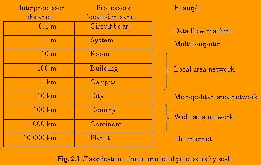
An alternative criterion for classifying networks is their scale. In the Fig. 2.1 we give a classification of multiple processor systems arranged by their physical size. At the top are data flow machines, highly parallel computers with many functional units all working on the same program. Next come the multicomputers, systems that communicate by sending messages over short, very fast buses. Beyond the multicomputer are the true networks, computers that communicate by exchanging messages over longer cables. These can be divided into local, metropolitan, and wide area networks. Finally, the connection of two or more networks is called an internetwork. The worldwide Internet is a well-known example of an internetwork.
2.1 TYPE OF NETWORKS
The networks can be broadly classified as local, metropolitan, and wide area networks on the basis of their scale.
2.1.1 Local Area Networks
Local area networks, generally called LANs, are privately owned networks within a single building or campus of upto few kilometers in size. They are widely used to connect personal computers and workstations in company offices and factories to share resources (e.g., printers) and exchange information. LANs are distinguished from other kinds of networks by three characteristics:
1) their size
2) their transmission technology, and
3) their topology.
LANs are restricted in size, which means that the worst-case transmission time is bounded and known in advance. Knowing this bound makes it possible to use certain kind of designs that would not otherwise be possible. It also simplifies network management.
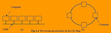
LANs often use a transmission technology consisting of a single cable to which all the machines are attached, like the telephone company party lines once used in rural areas. Traditional LANs run at speeds of 10 to 100 Mbps, have low delay, and make very few errors. Newer LANs may operate at higher speeds, upto hundreds of megabits/sec. Various topologies are possible for broadcast LANs. Fig. 2.2 shows two of them.
Some charateristics of LANs:
1) Typically connects computer in a single building or campus.
2) Developed in 1970s.
3) Medium: optical fibers, coaxial cables, twisted pair, wireless.
4) Low latency.
5) High speed networks (0.2 to 100 Mbps).
6) Speed adequate for most distributed systems.
7) Typically buses or ring.
2.1.2 Metropolitan Area Networks
A metropolitan area network or MAN is basically a bigger version of LAN and normally uses similar technology. It might cover a group of nearby corporate offices or a city and might be either private or public. A MAN can support both data and voice, and might even be related to the local cable television network. A MAN just has one or two cables and does not contain switching elements, which shunt packets over one of several potential output lines. Not having to switch simplifies the design. The main reason for even distinguishing MANs as a special category is that a standard has been adopted for them, and this standard is now being implemented. It is called DQDB (Distributed Queue Dual Bus) or for people who prefer numbers to letters, IEEE 802.6. DQDB consist of two unidirectional buses (cables) to which all the computers are connected, as shown in Fig.2.3. Each bus has a head-end, a device that initiates transmission activity. Traffic that is described for a computer to the right of the sender uses the upper bus. Traffic to the left uses the lower one.

A key aspect of a MAN is that there is a broadcast medium to which all the computers are attached. This greatly simplifies the design compared to the other kinds of networks.
Some characteristics of MANs:
1) Generally cover towns and cities (50 kms).
2) Developed in 1980s.
3) Medium: optical fibers, cables.
4) Data rates adequate for distributed computing applications.
5) A typical standard is DQDB.
6) Message routing is fast.
2.1.3 Wide Area Networks
A wide area network, or WAN, spans a large geographical area, often a country or continent. It contains a collection of machines intended for running user programs. These machines are called hosts. The term end system is sometimes also used in the literature. The hosts are connected by a communication subnet, or just subnet for short. The job of the subnet is to carry messages from host to host, just as the telephone system carries words from speaker to listener. By separating the pure communication aspects of the network (the subnet) from the application aspects (the hosts), the complete network design is greatly simplified.
In most wide area networks, the subnet consists of two distinct components: transmission lines and switching elements. Transmission lines (also called circuits, channels, or trunks) move bits between machines.
The switching elements are specialized computers used to connect two or more transmission lines. When data arrive on an incoming line, the switching element must choose an outgoing line to forward them on. Unfortunately, there is no standard terminology used to name these computers. They are variously called packet switching nodes, intermediate systems, and data switching exchanges, among other things.
In most WANs, the network contains numerous cables or telephone lines, each one connecting a pair of routers. If two routers that do not share a cable nevertheless wish to communicate, they must do this indirectly, via other routers. When a packet is sent from one router to another via one or more intermediate routers, the packet is received at each intermediate router in its entirety, stored there until the required output line is free, and then forwarded. A subnet using this principle is called a point-to-point, store-and-forward, or packet- switched subnet.
Some characteristics of WANs:
1) Generally cover large distances (states, countries. Continents).
2) Developed in 1960s.
3) Medium: communication circuits connected by routers.
4) Hosts are typically connected to (or close to) the routers.
5) Typical latencies: 100ms - 500ms.
6) Problem with delays if using satellites.
7) Typical speed: 20-2000 kbits/s.
8) Not (yet) suitable for distributed computing.
9) New standards are changing the landscape.
2.1.4 Internetworks
Many networks exist in the world, often with different hardware and software. People connected to one network often want to communicate with people attached to a different one. This desire requires connecting together different and frequently incompatible networks, sometimes by using machines called gateways to make the connection and provide the necessary translation, both in terms of hardware and software. A collection of interconnected networks is called an internetwork or just internet.
A common form of internet is a collection of LANs connected by a WAN.
2.2 NETWORK TOPOLOGIES
"The pattern of interconnection of nodes in a network is called the topology".
The selection of a topology for a network cannot be done in isolation as it affects the choice of media and the access method used. There are a number of factors to consider in making this choice, the most of which are set out below:
1) Cost
For a network to be cost effective, one would try to minimize installation cost. This may be achieved by using well-understood media and also, to lesser extent, by minimizing the distances involved.
2) Flexibility
Because the arrangement of furniture, internal walls etc. in offices is often subject to change, the topology should allow for easy reconfiguration of the network. This involves moving existing nodes and adding new ones.
3) Reliability
Failure in a network can take two forms. Firstly, an individual node can malfunction. This is not nearly as serious as the second type of fault where the network itself fails to operate. The topology chosen for the network can help by allowing the location of the fault to be detected and to provide some means of isolating it.
Many topologies have been developed and they can be divided into following two categories:
1) Static Topologies
2) Dynamic Topologies
2.2.1 Static Topologies
In conventional multicomputers, the network is static. This means the communication channels are built in hardware and are considered as fixed, at least for the run time of a particular algorithm.
With the possibilities of fast hardware-supported routing, some parallel computers offer virtual communication topologies, which are simulated by software within the true physical architecture. In this case, several virtual topologies may be used simultaneously.
1) Chain: We begin by arranging the processors in a linear array and connecting them to a chain, see Fig. 2.4

2) Ring: A chain is unsymmetric in the sense that the processors at the end of the chain have just
one connection link, while all others have two. This is avoided by closing the chain to a ring,
see Fig. 2.5

Depending on the type of connection we may further distinguish between unidirectional and bi-directional rings.
3) Chordal Ring: In a ring with large number of processors the distance may grow very large. One way to improve the situation is to increase the node degree. The node degree is the number of links at the node. In the ring we only have degree two at all nodes. By using a third link at each node, shortcuts for the communication in the ring can be built. The chordal ring of degree 3 is shown in Fig. 2.6

4) Barrel Shifter: By further increasing the node degree more shortcuts can be introduced. Alternatively to the chordal ring (of higher degree) we may then also consider the barrel shifter, see Fig.2.7 Here, the basic ring structure with N = 2k nodes is augmented by connections between all nodes i and j, whenever
| i - j | = 2k is an integer power of 2. The routing algorithms here are particularly elegant and efficient, however, the node degree will now increase with the size of the network.

5) Completely connected mesh: If the barrel shifter is still insufficiently connected, we may proceed to a completely connected graph, shown in Fig. Here any pair of processors is connected and the node degree of an N processor network is N-1. For large configurations (N large) a topology requiring N( N - 1 ) connections is not feasible.

6) Mesh Torus: Since so many algorithms for scientific computing use (multidimensional) arrays as data structures, it may seem natural to reflect this structure in the connection topology of a parallel machine. The simplest examples are of course the linear array (see1) and the ring (see 2). For problems in two physical dimensions a two-dimensional array of processors may be more suitable. Analogous to the ring, the mesh may be closed. The resulting structure is a mesh torus, see Fig. 2.9

For a 4 x 8 processor array a 3-dimensional picture of the graph is shown in Fig. 2.10

7) ILLIAC mesh: If the horizontal loops are closed in a spiraling form, we obtain the so-called ILLIAC mesh, see Fig.2.11, which happens to coincide with a chordal ring of degree 4.

8) Star: Another seemingly natural simple processor configuration is the star, see Fig. 2.12

9) Tree: Alternatively, the processors may be configured in a tree like structure, see Fig. 2.13

Both the star and the tree suffer from the bottleneck caused by the hierarchical structure for problems, which require large amounts of long distance communication. Here all the global communication must pass through one (or a few) nodes and their channels.
10) Fat Tree: For the tree a possible improvement is the so-called fat tree, see Fig. 2.14

The idea here is to alleviate the communication bottleneck at higher levels in the processor
hierarchy by increasing the communication bandwidth. Fig.2.14 suggests that this is done by
having multiple connections between the higher level nodes.
11) Cube: The last class of network topologies is a sequence of topologies the simplest of which is
the chain of two nodes. The next topology is then the 2 x 2 mesh and the 2 x 2 x 2 mesh in 3 dimensions, which becomes the cube in Fig.2.15 23 = 8 with nodes.

12) Hypercube: This sequence is naturally extended to the hypercube with nodes, as in Fig.2.16 The general topology is the d-dimensional hypercube with nodes.

13) Cube-connected cycle: The hypercube offers many interesting properties, in particular a communication distance between any two nodes of at most log2 (N) links for an N processor configuration. The increase in the node degree with log2 (N) , however, still a severe hardware problem for large N. A compromise which accepts somewhat longer communication distances while retaining the same basic structure is the cube-connected cycle, as are shown (for 3D) in Fig.2.17. Here the node degree is 3 for any size of the system.

2.2.2 Dynamic Topologies
In section 2.2.1 we have discussed static networks which cannot be changed once they are built. Networks, however, may also be dynamic. Such networks may be configured to set up connections between any pair of several components.
Typical devices with this functionality are:
1) Bus: The bus, which permits communication between any pair of devices connected to it.

However, a bus is an exclusive device, and whenever it services a communication between two devices, any other communication is blocked. Therefore a bus cannot be used with large number of processors. A bus however can broadcast messages; i.e. it can send a message to all devices connected to it.
2) Switching Network : Based on the binary switch in Fig. 2.19

with four possible states, it is possible to build complex switching networks. Fig. 2.20 shows an 8 x 8 switch
in a so-called baseline network.

In such a network up to eight connections may be used simultaneously, as long there is no access conflict. Not all combinations of connections however are possible simultaneously.
The complexity of the baseline network grows with N x log2N, where the depth of the network with log2N stages influences the latency of messages passing through the switch. Note that again broadcasts of messages from one sender to any of the output devices are possible.
3) Crossbar: Another device capable to perform the functionality of switching from N input to N output devices is the crossbar. Here a grid is built and any connection from an incoming line to an outgoing line can be made.

The crossbar has complexity N x N and saves the log2N intermediate stages of a baseline net. Due to the regular structure it is fairly simple to build, say on a specialized routing chip. However, a crossbar connecting a large number of processors a large number of memory modules where each of the lines in Fig. 2.21 would also represent a bus of say 128 bit width would quickly reach technological limits in its complexity.
4) Multi-bus system: The wide availability of buses e.g. in the form of Ethernet installations make it attractive to devise networks where buses are used. The primary feature of a bus is that though only one connection can be serviced at any time, a potentially large number of devices can be connected to it. If we think of ethernet as a cheap network technology, the reverse is true for the processing nodes. Typically the number of networks, a workstation can be connected to is very limited. For entry level machine it may be just one, and even for larger ones it is only two. However, the number of workstations that can be connected to an ethernet is almost unlimited. Thus it is a nice idea to reverse the role of networks and workstations.

Fig. 2.22 shows the so-called em dual hypercube for dimension 3, where the edges represent computers and the corners represent the different ethernets. This configuration retains several of the features of a hypercube. However, while the number of networks is now 2d and each computer needs exactly two ethernet connections, the number of computers required is d2d-1.
2.3 COMMUNICATION CHANNELS
By communication channels of network, it is meant that the "connecting cables" are being talked about. The cables that connect two or more workstations are the communication channels.
In LANs (i.e., very small networks) many different types of media are in use. Copper conductors in the form of twisted pair or coaxial are by far the most common. More recently, very serious consideration has been given to the use of optical fiber technology in LANs. Other media e.g., microwave transmission, infrared, telephone line etc. are also used. The basic types of cables are being discussed below.
2.3.1 Twisted Pair Cable
The most common form of wiring in data communication application is the twisted pair cable. As a Voice Grade Medium (VGM), it is the basis for most internal office telephone wiring. It consists of two identical wires wrapped together in a double helix.
Problems can occur due to differences in the electrical characteristics between the pair (e.g., length, resistance, capacitance). For this reason, LAN applications will tend to use a higher quality cable known as Data Grade Medium (DGM).
The main advantages of twisted pair cable are its simplicity and ease of installation. It is physically flexible, has a low weight and can be easily connected.
The data transmission characteristics are not so good. Because of high attenuation, it is incapable of carrying a signal over long distances without the use of repeaters. Its low bandwidth capabilities make it unsuitable for broadband applications. Fig. 2.23 shows a twisted pair cable.

2.3.2 Coaxial Cable
This type of cable consists of a solid wire core surrounded by one or more foil or wire shields, each separated by some kind of plastic insulator. The inner core carries the signal, and the shield provides the ground. While it is less popular than twisted pair, it is widely used for television signals. In the form of (CATV) cable, it provides a cheap means of transporting multi-channel television signals around metropolitan areas. It is also used by large corporations in building security systems.
The data transmission characteristics of coaxial cable are considerably better than those of twisted pair. This opens the possibility of using it as the basis for a shared cable network, with part of bandwidth being used for data traffic. Fig. 2.24 shows a coaxial cable.

2.3.3 Optical Fibers
Optical fibers consist of thin strands of glass or glass like material, which are so constructed that they carry light from a source at one end of the fiber to a detector at the other end. The light sources are either light emitting diode (LEDs) or laser diodes (LDs). The data to be transmitted is modulated onto the light beam using frequency modulation techniques. The signals can then be picked up at the receiving end and demodulated. The bandwidth of the medium is potentially very high. For LEDs, this ranges between 20 and 150 mbps and higher rates are possible using LEDs.
The major problems with optical fibers are associated with installation. They are quite fragile and may need special care to make them sufficiently robust for an office environment. Connecting either two fibers together or a light source to a fiber is a difficult process.
One of the major advantages of optical fibers over other media is their complete immunity to noise, because the information is travelling on a modulated light beam.
A side effect of this noise immunity is that optical fibers are virtually impossible to tap. In order to incept the signal, the fiber must be cut and a detector inserted.
Despite its shortcomings, optical fiber is an important technology and will be a very attractive transmission indeed.

2.4 NETWORK HARDWARE COMPONENTS
As we implement a computer network, there are various requirements that are a must for establishing a network. Requirements are both hardware and software related. Some common requirements are:
1) Connect networks of different types, different vendors.
2) Provide common communication facilities and hide different hardware and protocols of constituent networks.
3) Needed for extensible open distributed systems.
Different hardware components are required for accomplishing the above requirements. Some of them are network interface card, hub, repeater, switch, bridge, router, gateway etc.
2.4.1 Network Interface Card
A network interface card is used to connect a computer to an Ethernet network. The card (shown in the
Fig. 2.26) provides an interface to the media. This may be either using an external transceiver (as shown) or through an internal integrated transceiver mounted on the network interface card PCB. The card usually also contains the protocol control firmware and Ethernet Controller needed to support the Medium Access Control (MAC) data link protocol used by Ethernet.

Ethernet source address
Each network interface card is assigned an Ethernet source address by the manufacturer of the network interface card (this is normally stored in a PROM on the network interface card). The addresses are globally unique, and are assigned in blocks of 16 (or 8) million addresses to the Ethernet interface manufacturers, according to a flat addressing structure. This ensures that no two Ethernet network interface will ever have the same source address.
2.4.2 Repeater
A repeater is a device that amplifies a signal being transmitted on the network. It is used in long network lines, which exceed the maximum rated distance for a single run.

Over distance, the cables connecting a network lose the signal transmitted. If the signal degrades too much, it fails to reach the destination. Or if it does arrive, the degradation of the message makes it useless. Repeaters can be installed along the way to ensure that data packets reach their destination. Repeaters are of two kinds amplifier and signal repeater. The first merely amplifies all incoming signals over the network. However, it amplifies both the signal and any concurrent noise. The second type collects the inbound packet and then retransmits the packet as if it were starting from the source station.
2.4.3 Hub
A Hub is nothing but a multi-port repeater.
Fig. 2.28 shows a hub connecting three computers.

2.4.4 Bridge
A bridge is a device that lets you link two networks together. Bridges are smart enough to know which computer is on which side of the bridge, so they only allow those messages that need to get to the other side to cross the bridge. This improves performance on both sides of the bridge. As a packet arrives at the bridge, the bridge examines the physical destination address of the packet. The bridge then decides whether or not to let the packet cross.
Bridge is an intelligent device that view at the data inside the transmissions. Such bridges have only two connectors, allowing splitting large networks into two smaller sub-networks. Fig. 2.29 shows a bridge.

2.4.5 Switch
Switches are also intelligent, but are able to handle more than two ports and are able to handle more than two communications at the same time.
When a transmission comes in one port, the switch looks at the MAC address to determine, onto which port to send it out.


2.4.6 Router
A device that works like a bridge but can handle different protocols is known as a router. For example, a router can link Ethernet to a mainframe.
If the destination is unknown to a router it sends the traffic to another router which knows the destination.
A router differs from a bridge in a way that former uses logical addresses and the latter uses physical addresses.
A router is an Intermediate System (IS) which operates at the network layer of the OSI reference model. Routers may be used to connect two or more IP networks, or an IP network to an internet connection.
A router consists of a computer with at least two network interface cards supporting the IP protocol. The router receives packets from each interface via a network interface and forwards the received packets to an appropriate output network interface. Received packets have all link layer protocol headers removed, and transmitted packets have a new link protocol header added prior to transmission.
The router uses the information held in the network layer header (i.e. IP header) to decide whether to forward each received packet, and which network interface to use to send the packet. Most packets are forwarded based on the packet's IP destination address, along with routing information held within the router in a routing table. Before a packet is forwarded, the processor checks the Maximum Transfer Unit (MTU) of the specified interface. Packets larger than the interface's MTU must be fragmented by the router into two or more smaller packets. If a packet is received which has the Don't Fragment (DF) bit set in the packet header, the packet is not fragmented, but instead discarded. In this case, an ICMP error message is returned to the sender (i.e. to the original packet's IP source address) informing it of the interface's MTU size. This forms the basis for Path MTU discovery (PMTU).
The routing and filter tables resemble similar tables in link layer bridges and switches. Except, that instead of specifying link hardware addresses (MAC addresses), the router table specify network (IP addresses). The routing table lists known IP destination addresses with the appropriate network to prevent unauthorized access from remote computers by discarding packets to specified destination address.
A router forwards packets from one IP network to another IP network. Like other systems, it determines the IP network from the logical AND of an IP address with the associated subnetwork address mask. One exception to this rule is when a router receives an IP packet to a network broadcast address. In this case, the router discards the packet. Forwarding broadcast packet can lead to severe storms of packets, and if uncontrolled could lead to network overload.
A router introduces delay (latency) as it processes the packets it receives. The total delay observed is the sum of many components including:
> Time taken to process the frame by the data link protocol
> Time taken to select the correct output link (i.e. filtering and routing)
> Queuing delay at the output link (when the link is busy)
> Other activities which consume processor resources (computing routing tables, network management, generation of logging information)
The router queue of packets waiting to be sent also introduces a potential cause of packet loss. Since the router has a finite amount of buffer memory to hold the queue, a router which receives packets at too high a rate may experience a full queue. In this case, the router ahs no other option than to simply discard excess packets. If required, these may later be retransmitted by a transport protocol.

Routers are often used to connect together networks that use different types of links (for instance an HDLC link connecting a WAN to a local Ethernet LAN). The optimum (and maximum) packet lengths (i.e. the Maximum Transfer Unit (MTU)) are different for different types of network. A router may therefore uses IP to provide segmentation of packets into a suitable size for transmission on a network.
Associated protocols perform network error reporting (ICMP), communication between routers (to determine appropriate routes to each destination) and remote monitoring of the router operation (network management).
2.4.7 Gateway
A gateway is a device that connects dissimilar networks. A gateway operates at the highest layer of network abstraction. It expands the functionality of routers by performing data translation and protocol conversion. It is needed to convert Ethernet traffic from the LAN to SNA (Systems Network Architecture) traffic on a legacy system. It then routes the SNA traffic to the mainframe. When the mainframe answers, the reverse process occurs.
back...
|