 |
|
|
|
|
|
|
|
|
|
|
|
|
|
|
|
|
|
|
|
|
|
|
|
|
|
|
|
|
|
|
|
|
|
|
|
|
|
|
|
|
|
|
|
|
|
|
|
|
|
|
|
|
|
|
|
|
|
|
|
|
|
 |
|
Plumbing |
|
|
|
|
 |
|
|
|
|
|
|
Fuel Line Plumbing |
|
|
Brake Line Plumbing |
|
|
|
|
|
|
 |
|
|
 |
|
|
|
|
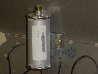
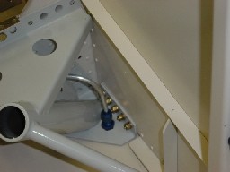
Here the Brake Reservoir is mounted on the engine side of the firewall. There is a fitting at the bottom of the reservoir that passes through the firewall to the inside of the cabin, to supply fluid to the brake system. |
|
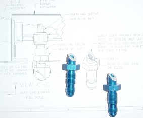
I started the fuel line plumbing with the tank vent lines. It just seemed easier to start there and work backwards. The vent lines for the fuel tanks terminate under the fuselage. The ends of the lines have a 45 degree angle cut into them that face into the wind to keep positive pressure in the tanks. The angles had to be cut at the end of a fitting. |
|
|
|
|
|
 |
|
|
|
 |
|
|
|
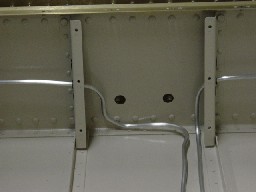
The brake line bracket is mounted to the firewall on the inside. Thses fittings are where the flexible lines from the brake pedal master cylinders, will connect to the aluminum lines that will go to the main gear wheel brakes. |
|
Here is the termination of the vent line for the left tank. The fitting is mounted under the fuselage. Sorry for the out of focus picture. |
|
|
|
|
|
 |
|
|
|
|
 |
|
|
|
|
|
After I unstalled the main gear weldments, I was able to put the fittings for the brake lines and install the lines from the fitting to the firewall bracket. |
|
|
|
|
|
|
 |
|
|
|
The fuel tank vent line for the left tank, is routed up to the top of the inside of the cabin before it is routed back down. The vent line has to run higher than the fuel tank to keep from siphoning the fuel out of the tank. |
|
|
|
|
|
 |
|
|
|
|
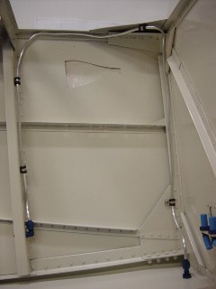
Brake line routing through the center cabin. |
|
|
|
|
|
 |
|
|
|
|
|
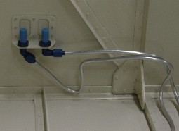
Brake lines terminating at the firewall bracket. Here the plastic lines from the brake pedals will connect. |
|
|
|
|
|
|
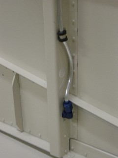
Here is a close up of the bend in the line just before the elbow. It is hard to see in the picture, but there is a hole there where the rudder cable passes from the rudder pedals. The curve around the hole is to make sure the two do not interfere with each other. |
|
|
|
|
 |
|
|
|
|
|
|
 |
|
|
|
|
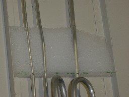
In the center tunnel for the lines, a foam block is used to isolate the fuel and brake lines and dampen vibrations. This picture shows one block, there are actually two installed. Mating pieces are attached to the tunnel cover |
|
|
|
|
|
|
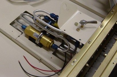
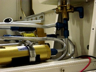
I installed the high pressure fuel pump and ran the fuel lines through the filter, selector switch, and back to the firewall. |
|
|
|
|
|
More will follow below as I install the brake lines. In the meantime I am adding to the right column which is the fuel tank plumbing. |
|
|
|
 |
|
|
|
|
|
Above is a close up of the lines going to the selector switch. The open elbow connections at the top will go out to the wings when I attach them. I also need to add a return line for the excess fuel. I am going to run a single line to one tank. I will put the additional plumbing under the firewall forward section or wings section. |
|
|
|
 |
|
|
|
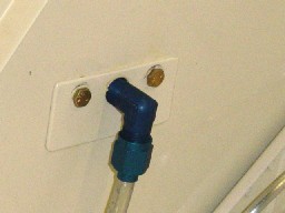
One last picture of the fuel line going through the firewall. I will seal around the penatration with proseal after all the firewall penatrations are complete. |
|
|
|
 |
|
|
|
 |
|
|
|
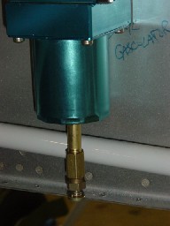
On the firewall forward side I extended the drain for the gascolator. I used a 2" brass NPT fitting, a coupler, and a CAV110 from Vans. This placed the drain position at the lowest point in the system, and made is accessable from the bottom of the cowling (when I put it on!) |
|