 |
|
|
|
|
|
|
|
|
|
|
|
|
|
|
|
|
|
|
|
|
|
|
|
|
|
|
|
|
|
|
|
|
|
|
|
|
|
|
|
|
|
|
|
|
|
|
|
|
|
|
|
|
|
|
|
|
|
|
|
|
|
|
|
Landing Gear Installation |
|
|
 |
|
|
|
|
|
 |
|
|
|
|
|
|
Main Gear |
|
|
 |
|
|
|
|
|
|
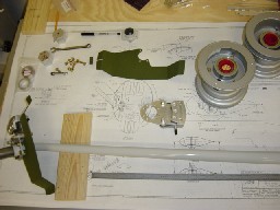
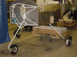
I am building a 9A, which is a tricycle gear plane. The main gear legs are attached to weldments attached to the main spar.
The picture to the left shows the right gear leg with several inboard pieces installed, waiting for the wheel to be placed on the axel. The pieces for the left gear leg are shown in the top of the picture along with the Cleveland wheels. |
|
|
|
|
 |
|
|
|
|
|
|
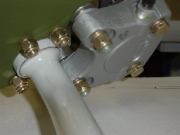
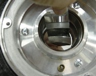
The picture to the left shows the inboard section of the gear leg, with the wheel pants attach bracket (primed green) bolted to the brake flange, and the Cleveland Brake assembly setting on the pins of the brake flange. |
|
|
|
|
|
 |
|
|
|
I used a little baby power on the intertube to keep it from binding on the inside of the tire as it was inflated. The intertube was inflated several times to make sure it fit properly inside the tire. |
|
|
|
|
|
 |
|
|
|
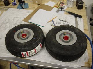
Both tires completed and inflated. I removed and repacked the wheel bearings too. They appeared to be packed ok, but the instructions were clear to repack them so I did. |
|
|
|
|
|
 |
|
|
|
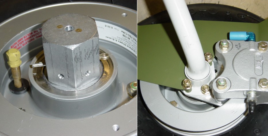
The front and rear of the completed assemblies. It took a lot more work to get here than you may think (at least more than I thought it would.) After the wheels were mounted on the axel, the nut had to be put on and adjusted for no play in the bearings, but still allowing the wheel to spin freely. This was not a problem, however then you have to mark the axel (centerpunch) for the cotter pin hole. Sounds easy, but you screw up the threads in doing so and it is difficult to get the nut back off. Anyway, thanks to Dan Checkoway's RV-7 site, I knew what I was in for ahead of time and was ready for it. You can see some scoring on the nut in the above picture from the wrench I used to get it off with. It still took me quite a while to get the holes drilled properly, but I knew what I was in for, and ready for it. -- Thanks Dan ! |
|
|
|
 |
|
|
|
Nose Wheel |
|
|
|
|
|
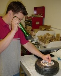
Putting the nosewheel together was a challenge itself. The tire bead fits very tightly on the wheel halfs. So what happens when you try to put the wheel halfs together is the tube can eaisly get pinched in between the halfs as you assemble them. The tire does not have enough room in it to fit the tube until the bead is all the way onto the wheel (if all this makes sense.)
Anyway, the trick we found after one failure and one tube later, is we used molly bolts through the wheel bolt holes (because they were longer,) and we slowly moved the halfs together while we inflated and deflated the tube. As we inflated the tube, it would move the tire bead further up the wheel. Then we deflated the tube which got it mostly out of the way of the wheel halfs comming together. Then we tightened the wheel halfs a little more, then inflated the tube again which moved the bead a little more up the wheel and gave the tube a little more room. We repeated this process until the bead was all the way on the wheel, then deflated it one last time, removed the molly bolts and put the AN bolts in and made the assembly complete.
The top picture shows the molly bolts which made it easy to slowly tighten the wheel halfs as we worked the tire bead up the wheel. The second and third pictures show us checking the tube to make sure it is not pinched as we go.
Vans had actually sent two tubes for the noswheel. It was on the inventory that way. I wondered why they sent two, and now I know. Must be everyone ruins the first on, as I did, trying to get the process down.
Afterwards I mounted the gear leg into the engine mount weldment. |
|
|
|
|
 |
|
|
|
|
|
 |
|
|
|
|
|
 |
|
|
|
|
|
 |
|
|
|
|
|
|
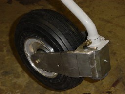
I installed the nosewheel on the nose gear leg. I've yet to set the "break out" force, which is basically how tight to tighten the nut on the bottom. |
|
|
|
|
|
 |
|
|
|
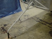
Here it is on all three legs. It feels good to get it to this point. |
|
|
|
|
|
 |
|
|
 |
|
|
|
|
|
|
 |
|
|
|
|
|
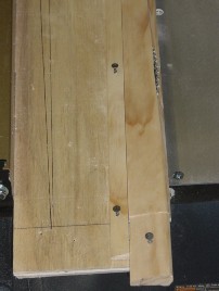
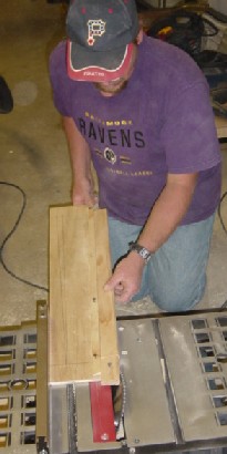
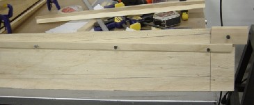
Wooden stiffeners for the gear legs are being constructed here. The purpose of the stiffeners is to dampen vibrations in the steel landing gear during taxi. The stiffeners were made out of window moulding since the shape of the molding is a good start for the shape needed for the stiffener. Two pieces make up each stiffener. The pieces are tapered from top to bottom, and the leading edges have a 30 degree angle cut to make it easy to fit and bond to the gear leg. This compund cut required making a jig (right 2 pictures above) then cut on a table saw at 30 degrees. My brother Allen built the jig and made the cuts (above left.) |
|
|
|
 |
|
|
|
The mating pieces are clamped and bonded together (left,) prior to sanding and bonding to gear leg. |
|
|
|
|
|
 |
|
|
|
 |
|
|
|
|
|
 |
|
|
|
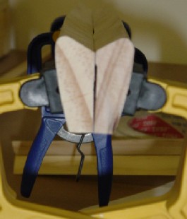
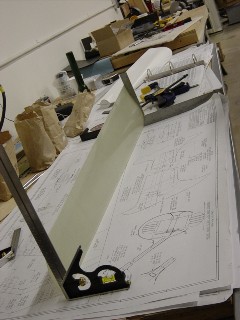
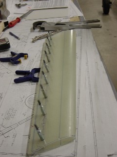
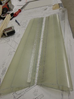
These 3 pictures are the construction of the main gear leg fairings.
Above Left: The molded faining is squared and marked so there will be no twist in it during construction.
Above: A hinge is drilled and riveted to the inside of the fairing. The drilling of the hinge is when it is important to keep the twist out of the fairing. The marks made earlier help keep it aligned.
Left: Both completed main fairings. A templete was used to get the right shape (some additional trimming will be required later.) The hinge serves to close the fairing on the training edge. To install or remove the fairing, you simply remove the hinge pin and the fairing will open up. Once installed the hinge will keep the fairing closed. |
|
|
|