 |
|
|
|
|
|
|
|
|
|
|
|
|
|
|
|
|
|
|
|
|
|
|
|
|
|
|
|
|
|
|
|
|
|
|
|
|
|
|
|
|
|
|
|
|
|
|
|
|
|
|
 |
|
|
|
Empennage Mounting on Fuselage |
|
|
|
|
 |
|
|
|
|
|
|
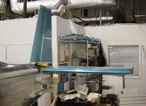
Now is the time to mount the empennage onto the fuselage. I am going to mount it here in the shop to set up the controls, fairings, and wiring. After it is complete I will take it back apart as I will not be able to get it out the dock door with the tail on. Once I get it to the hanger at the airport I will re-install it |
|
|
|
 |
|
|
|
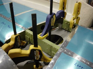
The Horizontal Stab was mounted to the fuselage rear deck and clamped in place. The tips of the HS was measured from each side to points on the firewall and adjusted, to make sure the HS was square on the fuselage deck. The Spars were drilled to the the deck and rear support. |
|
|
|
|
|
 |
|
|
|
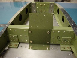
After the HS was bolted to the deck, the VS support bracket F-981 was cleaned, primed and mounted to the HS front spar and deck.
Notice the offset from center on the VS mounting to accomodate the left turning nature of single engine prop planes. |
|
|
|
|
|
 |
|
|
|
The rear spar of the HS was bolted to the uprights already completed in the quickbuild kit. The spacing was 11/32" from the deck to the bottom of the spar. The spacing was easy to get as Vans suggested just using an 11/32" drill bit laying on the deck as a spacer. |
|
|
|
|
|
 |
|
|
|
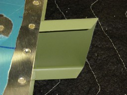
To prepare the VS for mounting, the end of the front spar had to be trimmed at an angle to match the angle it will mate with the top of the HS front spar. |
|
|
|
|
|
 |
|
|
|
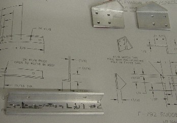
At this point I went ahead and made the rudder stops, and the up elevator stop. It seemed I had about the right amount of time available, so I made them..
|
|
|
|
|
|
 |
|
|
|
The VS is clamped to the fuselage and ready for alignment. This will be done a little later when I can get someone to help me (two man job.) |
|
|
|
|
|
 |
|
|
|
I mounted the elevators onto the HS, and WOW it is really starting to look like an airplane. (Picture will follow). |
|
|
|
|
|
 |
|
|
|
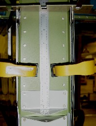
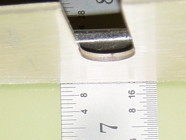
The Vertical Stabilizer was set on the fuselage. I set my rule on top of the lower hinge, and used a flat piece of scrap material across the longerons so I can set the vertical height of the rear spar. |
|
|
|
|
|
 |
|
|
|
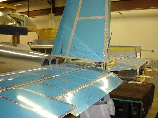
I set the height at 7 11/32" per the drawing, then measured from the tips of the VS rear spar to the tips of the HS rear spar to square the rudder. I had to do this in a few iterations as each adjustment moved the other a little. Finally I got it all square. The measurement from the VS rear spar tips to the HS rear spar tips was 68 1/8" on each side. |
|
|
|
|
|
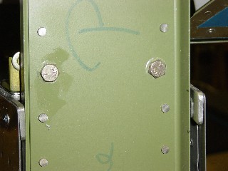
After the alignment was clamped in place, I drilled the rear spar to the elevator up travel limit bracket.
The fron spar was also drilled to the F-981 attach bracket after the positionong was adjusted to keep the rudder hinges on the rear spar aligned.
The front of the VS is offset a little to the left to compensate for P factor, so you see here a washer that is being used to take up a little of the space on the rear spar because of it. - Of course the washer shown here is temporary. On final assembly, the attach bolt will pass through it. |
|
|
 |
|
|
|
|
|
 |
|
|
|
|
|
|
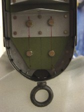
The lower part of the rear spar of the vertical stabilizer bolted in place with the tail tie down installed. |
|
|
|
|
|
 |
|
|
|
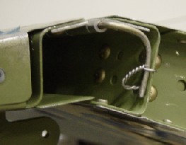
After mounting the elevators, I secured the trim tab hinge pin by forming it as shown in the drawing, and safety wiring it to the elevator. Vans said it would be easier to bend if you heat it up with a torch first. I didn't have a torch, but I had good luck (for a change) using two vice grips. |
|
|
|