The following is an alteration done to one of my Reflexs. This is for informational purposes only.
Any modifications are done at your own risk. Check local laws for restrictions on some of these changes.
Turn Signal Beeper:
PROBLEM:
I was used to the large turn indicators on the Helix and the ones on the Reflex are sometimes hard to see.  I would accidentally leave the signal on after turn.
SOLUTION:
Installation of an audible indicator.
TOOLS / EQUIPMENT NEEDED:
Audible indicator
( Mine was called Extra Loud Electronic Beeper Part #01PP3561X from JCWhitney for $24.98 ) Picture TS1
Phillips Screw Driver
Wire Terminal Connectors ( 2 butt splice terminals, 1 U-end terminal, and two inline splice connectors )
Wire terminal connector tool
Wire ties
Electrical tape
Wire
DIFFICULTY RATING:
Easy
INSTRUCTIONS:
Select a suitable location for the audible indicator.
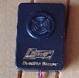
( Mine was on the dash between the windscreen and the dash. Instructions are to install mine yours may differ slightly depending on the device.  )

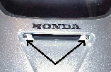
1.  Remove windshield cowl
      A.  Two screws in indentation under Honda label on front (Picture TS2 ) and
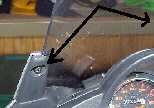
      B.  Two screws on either side high above instrument cluster ( Picture TS3 )

2.   Place audible indicator ( double stick tape ) and run wires inside fairing toward front turn signals. ( Picture TS4 )

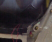
3.   Reach under fairing and gently remove turn signal wires ( there is a retaining tab do not break it off ) ( Picture TS5 )

4.   Cut off or back protective wrap to expose wires.
      
There are three wires Green is ground, middle is running light, and third wire is turn signal wire.

5.   Use inline splice connector to tap into turn signal wire and run it back to audible indicator.

6.   Use wire ties and tie it to existing wires where possible.

7.   Use tape to protect the wires as they were before you cut back plastic in step 4

8.   Use the above steps 3-7 for the other side.

9.   One wire from audible indicator must be connected to ground location.

10.  Test device, if it works continue if not check your steps again 

11.  Secure the remaining wires out of sight.

12.  Replace cowl and your done.
Click on image for larger view
Click on Image for larger view
Picture TS1
Picture TS2
Picture  TS3
Picture TS4
Picture TS5
Click here to return to home page
  
If you need a larger view of any of the pictures on these pages E-Mail me with the picture number and I will send it to you.
Hosted by www.Geocities.ws

1