The following figure shows the prototype block diagram:
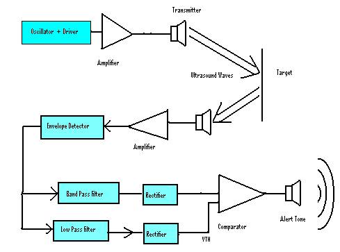
Figure 1: Prototype
Block diagram
The following figure shows the prototype block diagram:
The following section includes all the calculations for the motion detector system:
Band Width
Calculations:
Speed range desired = 6 ft/sec to 30 ft/sec.
6 ft/sec = 1.8288 m/s
30 ft/sec = 9.144 m/s
Doppler effect:
f’ = fo (v +/- vo) / (v +/- vs)
fo = center frequency = 25 kHz.
v = speed of sound = 340 m/s
vo = speed of object.
vs = speed of source = 0 m/s
When
the person is running toward the detector:
f1’ = 25 (340+1.8288)/340 = 25.134 kHz
f2’ = 25 (340 + 9.144)/340 = 25.673 kHz
When the person is running away from the detector:
f1’ = 25 (340-1.8288)/340 = 24.87 kHz
f2’ = 25 (340 - 9.144)/340 = 24.33 kHz
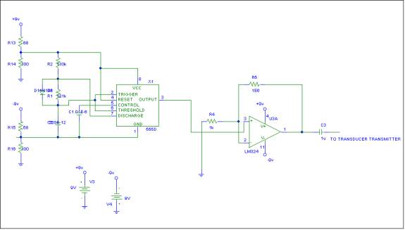
555D was used as an oscillator with frequency of 25 kHz and a duty cycle of 50%
The
output is high for t1 seconds:
t1(secs)=K*Ra*C/1000
K is worked out by the server and is calculated from Vcc and Vdd.
The output is low for t2 seconds:
t2(secs)=0.693*Rb*C/1000
Where R is in K Ohms and C is in uF (micro Farads).
Vcc = 9V
C = 220 pF
Ra = 110 kW
Rb = 131 kW
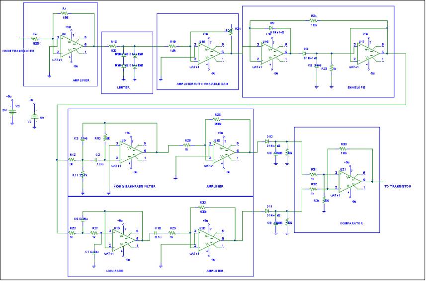
Comparator:
Av = 100 V/V
R1 = 1 kW
R2 = 100 kW
Vo = -(R2/R1) (vi1 – vi2)
vi1 = Output of envelope detector.
vi2 = Output of band pass filter.
Butterworth
high Q band pass filter:
K = gain = 1
f0 = (673+134)/2 = 404 Hz
w0 = 2pf0 = 2538.41 rads/sec
b = 2p(673) - 2p(134) = 3386.64 rads/sec
Q = w0/b = 0.75
R1’ = Q/K = 0.75 W
R2’ = Q/(2Q^2 –K) = 6W
R3’ = 2Q = 1.5 W
C = 0.1 uF
Kf = 2pfo = 2538.41 rads/sec
R1 = Km R1’ = (107 / 2538.41) * 0.75 = 3kW
R2 = Km R2’ = (107 / 2538.41) * 6 = 23.7kW
R3 = Km R3’ = (107 / 2538.41) * 1.5 = 6kW
Low Pass Filter:
Low pass filter with a cut off frequency = 1.5 kHz and gain = 100V/V
When
R = 1 W
and w = 1 rad/sec
(2)^0.5 = 1/C1 C1 = 1.4142 F
C2 = 1/C1 = 0.7071 F
When
f = 1.5 kHz:
Wc = 9424.7 rad/s
kf = 9424.7 km = 1000 = R’/R
C1’ = 1/(hm hf) C1 = 0.15 uF
C2’
= 1/(hm hf) C2 = 0.08 uF
The Transistor Circuit that controls the Buzzer:
b
= 140
Ic
= (9 - 2)/1.2 = 5.8 mA
a = b
/ (b
+ 1) = 0.993
IE
= Ic / a = 5.875 mA
IB
= IE – IC = 0.042 mA
RB
= (1.5 – 1.2) / 0.042 = 7.14 kW
RE
= 0.5 / IE = 85 W
Rs
= 1kW
Later through the year, I will designed the motion detector by using micro controllers. This project was done in six weeks through the summer with a group of three.
![]()