INTRODUCTION:
The overall objective of this Experiment is to familiarize
the equipment and ADC devices.
The Pic 16C711 would be configured as an ADC and interfaced with the computer
Other components necessary include resistors of varies values and capacitors.
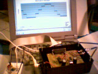
The equipment needed for the experiment is shown below.
|
Equipment |
Description |
||
|
Power Supply |
single power supply |
Vmax |
5V |
|
|
Vmin |
0 |
|
|
O Scope |
100 MHz oscilloscope |
||
|
Components |
16C711 , CD4016 , TI 082 |
||
|
DMM |
|
||
DESCRIPTION:
Figure
2. Michael’s Oscope Block Diagram
The
different stages are described in the following outline:
· Input Buffer: This component has two functions. The first function is to divide the voltage so the sample and hold op-amp does not go to saturation. When the signal enters the system, there is a resistor that opposes more than 20mA, and is divided by two zener diodes that only allow 2.4V peek to peek into the system. The capacitor separates the dc from the ac and the frequency response is 50Hz. The last two resistors act as an offset. This offset is very important for the op-amp is being supplied by a single power supply.
|
|
Note: There are two resistors on the input. The lower value resistor is for the 3Vpp and the higher value resistor is for 10Vpp. This is very important for the zener diodes have to operate under 20mA. The two resistor values for the offset is 10k ohms |
· Sample & Hold: The sample and hold is for creating a smooth transition from an analog signal to discrete digital signal. The PIC RA3 controls the sample analog switch. Also the specification from the micro controller calls for a sample and hold circuit so the conversion can operate efficiently.
|
|
Note: The output signal is on pin 7 of the second op-amp and the input is pin 5 of the first op-amp. The analog switch is the CD4016 chip. |
· ADC & Sampling triggering: The 16C711 micro controller controls the ADC and the sampling triggering. The first function that turns on when the micro controller is powered on is the sampling function. The pulse width of the sampling is controlled by the speed of the micro controller. The speed of the micro controller is two megahertz and this speed also affects the analog to digital converter as well. The second function turns off the sampling and starts the ADC. When the ADC complete flag turns on then the information is stored in an eight-bit resister. The last function before heading out to the computer is the eight-bit to four-bit conversion, which truncates the eight bit to four bit making a low resolution.
|
|
Note: The 16C711 is a micro controller that can be
erased by exposing the chip to ultraviolet light and reprogram the chip to
perform any updates. |
·
Computer Interfacing: When the computer receives the
information, the program stores three thousand entries. Then the information is
distributed to a graph. Where it is ploted to a voltage verses time graph. The
program is EXCEL with micros or with visual basic. The program is simple. When
the user clicks the start button the program records the information from the
parallel port and graphs it to the voltage vs time chart. The back draw from
this simple program is that the refreshing of the graph takes a long time. The
only way to speed up the process is to have a faster processor or the program is
done on visual C++.

| to learn more about microcontrollers go and check out http://www.microchipc.com/ |
| to Down load (Inpout32.zip) the driver I used. Go to http://www.lvr.com/parport.htm#Troubleshooting a Lakeview Research web site. It is Freeware that supports: port I/O. The file contains inpout32.dll. The Visual-Basic declarations are inp and out. I used an old PC with a 98 OS and I had no problems. |
![]()