
The system has five integrated circuits , and the
total current consumption is 29mA.
Figure 2. Alarm Block Diagram
The following outline describes the function for each block:
· Logic Control System: The function of the logic control system is to check the position of the toggle switch and to verify the status of the alarm. If any of the magnetic switches have been activated and the status of the alarm and toggle switches has been checked then the control switches the relay latching mechanism.
The control
logic system contains one AND gate 7408 chip, one OR gate 7432 chip, one NOT
gate 7404 chip, and a relay latching mechanism is on the circuit board that
control the alarm system. To protect it from outside factors such as dust and
water, it is place in a plastic box as small as possible according to the size
of the circuit and other components. The control panel is connected to the rest
of the elements of the alarm system. Small wire is used in order to reduce the
size of the circuit and to save space. The control panel is connected to the
power source that supplies electricity to the system.
·
Magnetic Contacts: Our demo contains two magnetic contacts.
The first one is located on the window and the other one is located on the door.
When the alarm is activated, and the normally closed circuit is opened, the
contact emits approximately five volts to the control system. The magnetic
switches for the door and the window are two separate systems. The door has a
ten second delay when the system is first activated, and has a ten second delay
when the homeowner presses the reentry button to reenter. The window is alarmed
when the toggle switch has been turned on. The two contacts are connected to the
logic control system through wires.
·
Key Switch: This component turns on the delay and activates
the logic control system of the security system. The key switch is located in
the main unit.
· Reentry Button: This component resets the delay so the homeowner can have ten seconds to deactivate the alarm. The location of the Reentry Button is outside the house away from the alarm system, which will only be known by the homeowner. The Reentry button is connected to the alarm system through wires.
·
Panic Button: This extra feature is when the burglar has
penetrated through the house without detection. The burglar then wants to make
an easy exit and touch the panic button thinking it is the off button. The panic
button bypasses the control system and turn on the relay latching mechanism.
There are various panic buttons all through the house, in the living room,
dining room, kitchen, bathrooms, and bedrooms. The panic button is connected to
the alarm system through wires.
·
Siren: This feature is located apart of the main unit of
the alarm system. It is connected through wires to the relay latching mechanism.
Whenever there is intrusion in the room, the system activates the relay latching
mechanism to provide current to either a sound generator or a crystal buzzer.
For simplicity of the design we implemented a buzzer.
·
Delay feature: The implementation of this feature is placed
in the control panel. The structure of the delay is a 555 timer synchronizing
the counter at one hertz. When the counter counts to ten, the alarm status of
the control system is activated. This extra feature allows the user to have a
delay period of ten seconds when the system is turned on.
·
LED: The LED indicator is connected to the delay. The
system is initially turned on the system is green and after the ten second delay
the system turns red and this is the indication for the homeowner that the
system is armed. The location of the LEDs is in the house.
To implement the first stage, the delay feature, we had to first implement a 555 timer by using a combination of resistors and a capacitor, so we could get a pulse that will be use later in a counter. The implementation of the 555 timer looks like this:
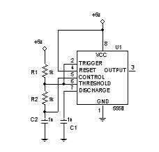
Figure 3. Timer Implantation
The 555 worked with 6 VCC, for specification look at appendix B for detail specifications. It has R1 and R2 = 1 KW and two capacitor C1 and C2 = 1 mF. Its output, pin number 3, was connected to the input of the counter. The 555 implementation was tested individually, passing the requirement needed for the project. The 555 timer is an essential part of the project because it supplies the counter with a clock pulse. The combination of these two gives the system an optional 10 seconds delays, needed to satisfy a specifications of the system. The combination of the counter with the 555 constitute the first stage of the system, the Delay stage, and its implementation is a follows:
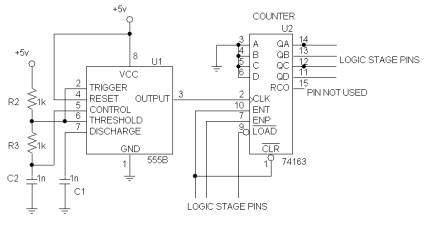
Figure 4. First Stage - Counter/555 Implementation
This schematic shows how the counter was implemented in respect to the other stages. The combination of the counter and the 555 was successfully individually tested, making a 10 seconds delay.
Also another
important stage of the system is the Logic stage, this was design using AND, OR
and NOR gates. Features of the system such as the magnetic window and door
switches, the toggle switch and the reentry button where incorporated in this
stage, making the design very compact and effective. This stage was tested and
its performance was very good, the results were as expected. The implementation
of this stage is as follows:
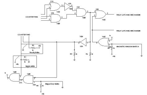
Figure 5. Second Stage- Logic Implementation
Anther important stage is the relay latching
mechanism, which is a given specification for the system design. This stage is
the connection between the logic stage and the buzzer. It has as part of its
implementation the Panic Button feature, located there for better circuit
performance. The stage was successfully tested and its implementation is as
follows:
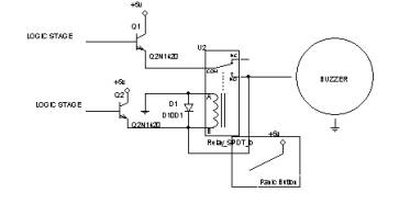
Figure 6. Third Stage - Relay Latching Mechanism
Finally the system comes with a battery backup, which was implemented in a way that when the ac input supply goes off it will automatically replace it, given input voltage to the system. This feature was individually tested, being successful. The schematic of this implementation is as follows:
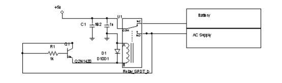
Figure 7. Power Supply/Backup Schematic
The final product became a totally success, all stages were put together
and tested, having great results. The results were as expected. The final
schematic is as follows:
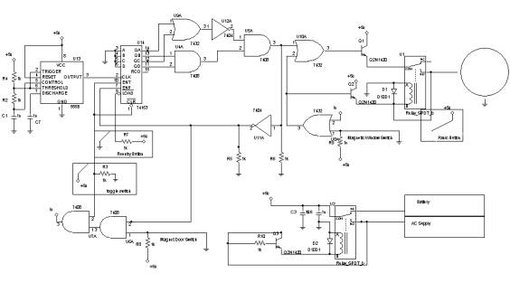
Figure 8. Alarm System's Final Schematic
![]()