|
Over a period of time, some people were skeptical about the transmission of timing signals through SDH. They hold the view that the internal oscillator frequency accuracy of SDH is not high enough, and SDH may be affected by the pointer adjustment, so it cannot be used for the transmission of timing signals. As a matter of fact, there are two misunderstandings here. First, the oscillator of SDH is at a subsidiary position in the network, which is the object to be synchronized. When tracing external reference signals in normal situation, the oscillator does not determine the frequency accuracy of the network. Second, the pointer adjustment is used to adapt the deviation between the service code flow clock and its own clock of the transmission equipment, so it only happens in the SDH payload and tributary signal. The synchronization network utilizes the SDH aggregate signal for timing, which does not generate pointer adjustment. Therefore, SDH can be used for transmission of timing signals, which has been proved by a lot of applications in the telecommunication network construction. To transmit timing signals through SDH, the first problem is the synchronization within the SDH transmission system itself. It should be ensured that no timing loop within the SDH transmission network occurs. Then use the SDH STM-N aggregate signal to carry the timing signal downwards and ensure that the upper clock would not be synchronized by lower clock during the transmission process of the synchronization network timing signal. As regarding to the quality of the timing signal transmitted through SDH network, so long as we stick to the principle that timing signals must be carried by the SDH STM-N aggregate signal, the effect on the timing quality by the SDH pointer adjustment will be avoided.
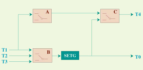
The clock performance of the SDH NE should comply with ITU-T G.813 and the timing function should comply with ITU-T G.783. The details are as shown in figure 1. T1 is the STM-N aggregate timing input interface, T2 the tributary timing input interface, T3 the external timing input interface, T4 the clock output interface, and T0 the internal clock.
Figure 1 Functional diagram of the SDH NE clock During the setup of the synchronization network, the two connection methods in figure 2 and figure 3 can be adopted for the SDH NE timing signal transmission.
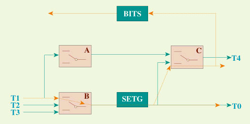
Figure 2 SDH transports timing
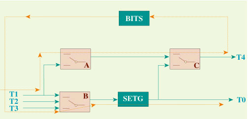
Figure 3 BITS connected serially with the SDH timing transport chain
The synchronous networking of SDH includes two aspects: synchronization network architecture based on the SDH network and timing signal transmission. The synchronization network architecture based on SDH network has been specified in ITU-T G.822. To determine synchronization clock specifications, the values for the worst-case synchronization reference chain are K = 10, N = 20, with the total number of SDH network element clocks limited to 60. Here, K is the number of BITS nodes and N is that of SDH NEs between two adjacent BITS nodes in the link. It should be noted, however, that in practical synchronization network design, the number of network elements in tandem should not exceed the defined maximum number in ITU-T Recommendations and should be minimized for reliability reasons. Because the timing loop should not be formed, it must be ensured that under any fault circumstances no timing loop occurs. Therefore, during SDH networking, all the SDH loops can be disconnected and taken as links. The check standard is also that the number of the longest timing chain should be. During SDH timing transport, the following principles and methods have to be complied with. SDH is both the serving object of the synchronization network and the carrier of the synchronization reference signal. The two aspects should not be separated. Therefore, the synchronization planning and design of the SDH network that acts as the transport link should be taken into consideration together with the design of the synchronization network. When designing the synchronization reference transport chain based on SDH network, it must be ensured that the timing loop or the phenomenon of upper clock being synchronized by lower clock does not occur under any fault situation (such as interruption of the transmission line, BITS fault and GPS invalidation). The affection under reference switching should be reduced as much as possible as well. The NE clock performance of SDH should comply with ITU-T G.813, the timing function should comply with ITU-T G.783, and the SSM function should comply with ITU-T G.781 respectively. The number of network elements and the BITS in tandem should not exceed the defined maximum number in ITU-T Recommendations and should be minimized for reliability reasons. The SSM information between SDH and BITS is transferred through the 2048kbits/s external synchronous interface of the SDH NE.
For the base station controller or base station whose node has been equipped with BITS equipment, the timing signal derived from the BITS equipment alone can satisfy the synchronization requirement of the network. For those the base station controller or base station that cannot be connected with the BITS equipment directly, the previous solution was deriving the timing signal from the services that were synchronized with the trunk input signal of the base station controller or base station. But because the services came from the tributary of the SDH equipment, there may be existed a lot of pointer adjustment and the clock quality may be rather bad. At present, the solution is to use the timing transmission method as figure 1 or 2 mentioned above, so the synchronization timing signal from BITS equipment is outputted to the clock input interface of the base station controller or base station through the T4 interface. For the base station controller or base station equipment that has no external clock input interface, the 2048kbit/s signal from the T4 interface can be accessed as a service to the base station controller or base station equipment. For the base station controller or base station equipment that has no external synchronous interface and is poor in service interfaces, you can only apply the other method such as re-timing from the upstream to adjust the service code flow so as to partly solve the clock problem. |