Following are recommended methods for securing grain as per international grain code
|
|
Longitudinal divisions (called shifting board), which must be grain tight may be fitted in both "filled" and "partly filled compartments". |
|
|
In "filled compartments, they must extend downwards from the underside of the deck or hatchcovers, to a distance below the deckline of at least one-eighth the breadth of the compartment, or at least 0.6m below the surface of the grain after it has been assumed to shift through an angle of 15o |
|
|
In a "partly filled compartment', the division, should extend both above and
below the level of grain, to a distance of one-eighth the breadth of the
compartment.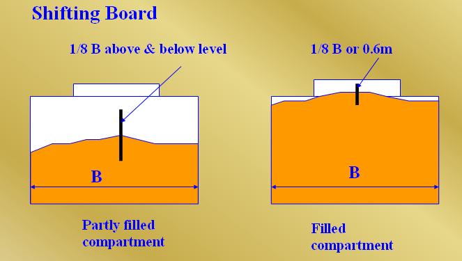 |
Figure: Shifting boards
14.1. For the purpose of reducing the heeling moment a saucer may be used in
place of a longitudinal division in way of a hatch opening only in a filled,
trimmed, compartment as defined in A 2.2, except in the case of linseed and
other seeds having similar properties, where a saucer may not be substituted for
a longitudinal division. If a longitudinal division is provided, it shall meet
the requirements of A 10.9.
14.2. The depth of the saucer, measured from the bottom of the saucer to the
deck line, shall be as follows:
.1. For ships with a moulded breadth of up to 9.1 m, not less than 1.2 m.
.2. For ships with a moulded breadth of 18.3 m or more, not less than 1.8 m.
.3. For ships with a moulded breadth between 9.1 m and 18.3 m, the minimum depth
of the saucer shall be calculated by interpolation.
14.3. The top (mouth) of the saucer shall be formed by the underdeck structure
in way of the hatchway, i.e. hatch side girders or coamings and hatch end beams.
The saucer and hatchway above shall be completely filled with bagged grain or
other suitable cargo laid down on a separation cloth or its equivalent and
stowed tightly against adjacent structure so as to have a bearing contact with
such structure to a depth equal to or greater than one half of the depth
specified in A 14.2. If hull structure to provide such bearing surface is not
available, the saucer shall be fixed in position by steel wire rope, chain, or
double steel strapping as specified in A 17.1.4 and spaced not more than 2.4 m
apart.
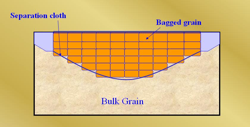
Fig: Saucers
. As an alternative to filling the saucer in a filled, trimmed, compartment with
bagged grain or other suitable cargo a bundle of bulk grain may be used provided
that:
.1. The dimensions and means for securing the bundle in place are the same as
specified for a saucer in A 14.2 and A 14.3.
.2. The saucer is lined with a material acceptable to the Administration having
a tensile strength of not less than 2,687 N per 5 cm strip and which is provided
with suitable means for securing at the top.
.3. As an alternative to A 15.2, a material acceptable to the Administration
having a tensile strength of not less than 1,344 N per 5 cm strip may be used if
the saucer is constructed as follows:
.3.1. Athwartship lashings acceptable to the Administration shall be placed
inside the saucer formed in the bulk grain at intervals of not more than 2.4 m.
These lashings shall be of sufficient length to permit being drawn up tight and
secured at the top of the saucer.
.3.2. Dunnage not less than 25 mm in thickness or other suitable material of
equal strength and between 150 mm and 300 mm in width shall be placed fore and
aft over these lashings to prevent the cutting or chafing of the material which
shall be placed thereon to line the saucer.
.4. The saucer shall be filled with bulk grain and secured at the top except
that when using material approved under A 15.3 further dunnage shall be laid on
top after lapping the material before the saucer is secured by setting up the
lashings.
.5. If more than one sheet of material is used to line the saucer they shall be
joined at the bottom either by sewing or by a double lap.
.6. The top of the saucer shall be coincidental with the bottom of the beams
when these are in place and suitable general cargo or bulk grain may be placed
between the beams on top of the saucer.
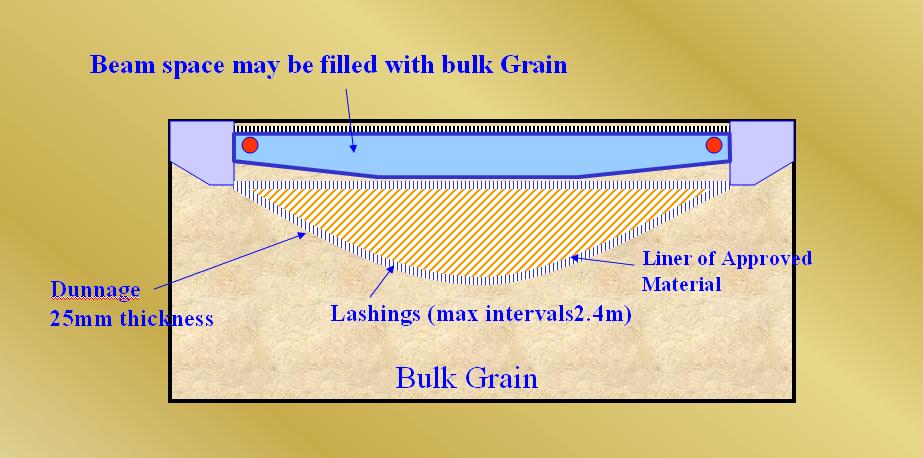
Figure: Bundling of bulk grain
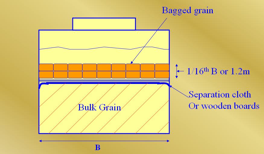
16.1. Where bagged grain or other suitable cargo is utilized for the purpose of
securing partly filled compartments, the free grain surface shall be level and
shall be covered with a separation cloth or equivalent or by a suitable
platform. Such platform shall consist of bearers spaced not more than 1.2 m
apart and 25 mm boards laid thereon spaced not more than 100 mm apart. Platforms
may be constructed of other materials provided they are deemed by the
Administration to be equivalent.
16.2. The platform or separation cloth shall be topped off with bagged grain
tightly stowed and extending to a height of not less than one sixteenth of the
maximum breadth of the free grain surface or 1.2 m, whichever is the greater.
16.3. The bagged grain shall be carried in sound bags which shall be well filled
and securely closed.
16.4. Instead of bagged grain, other suitable cargo tightly stowed and exerting
at least the same pressure as bagged grain stowed in accordance with A 16.2 may
be used.
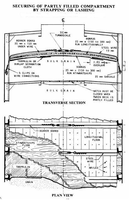
. When, in order to eliminate heeling moments in partly filled compartments,
strapping or lashing is utilized, the securing shall be accomplished as follows:
.1. The grain shall be trimmed and levelled to the extent that it is very
slightly crowned and covered with burlap separation cloths, tarpaulins or the
equivalent.
.2. The separation cloths and/or tarpaulins shall overlap by at least 1.8 m.
.3. Two solid floors of rough 25 mm x 150 mm to 300 mm lumber shall be laid with
the top floor running longitudinally and nailed to an athwartships bottom floor.
Alternatively, one solid floor of 50 mm lumber, running longitudinally and
nailed over the top of a 50 mm bottom bearer not less than 150 mm wide, may be
used. The bottom bearers shall extend the full breadth of the compartment and
shall be spaced not more than 2.4 m apart. Arrangements utilizing other
materials and deemed by the Administration to be equivalent to the foregoing may
be accepted.
.4. Steel wire rope (19 mm diameter or equivalent), double steel strapping (50
mm x 1.3 mm and having a breaking load of at least 49 kN), or chain of
equivalent strength, each of which shall be set tightly by means of a 32 mm
turnbuckle, may be used for lashings. A winch tightener, used in conjunction
with a locking arm, may be substituted for the 32 mm turnbuckle when steel
strapping is used, provided suitable wrenches are available for setting up as
necessary. When steel strapping is used, not less than three crimp seals shall
be used for securing the ends. When wire is used, not less than four clips shall
be used for forming eyes in the lashings.
.5. Prior to the completion of loading the lashing shall be positively attached
to the framing at a point approximately 450 mm below the anticipated final grain
surface by means of either a 25 mm shackle or beam clamp of equivalent strength.
.6. The lashings shall be spaced not more than 2.4 m apart and each shall be
supported by a bearer nailed over the top of the fore and aft floor. This bearer
shall consist of lumber of not less than 25 mm x 150 mm or its equivalent and
shall extend the full breadth of the compartment.
.7. During the voyage the strapping shall be regularly inspected and set up
where necessary.
|
|
It may be assumed that under the influence of ship motion underdeck voids
will be substantially filled by the flow of grain from a pair of
longitudinal feeders provided that:
|
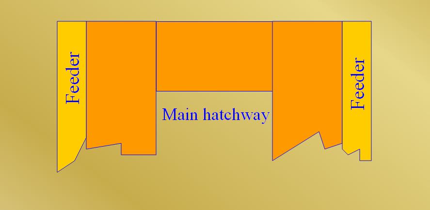
Fig: Feeders
. When, in order to eliminate grain heeling moments in partly filled
compartments, strapping or lashing is utilized, the securing may, as an
alternative to the method described in A 17, be accomplished as follows:
.1. The grain shall be trimmed and levelled to the extent that it is very
slightly crowned along the fore and aft centreline of the compartment.
.2. The entire surface of the grain shall be covered with burlap separation
cloths, tarpaulins, or the equivalent. The covering material shall have a
tensile strength of not less than 1,344 N per 5 cm strip.
.3. Two layers of wire reinforcement mesh shall be laid on top of the burlap or
other covering. The bottom layer is to be laid athwartships and the top layer is
to be laid longitudinally. The lengths of wire mesh are to be overlapped at
least 75 mm. The top layer of mesh is to be positioned over the bottom layer in
such a manner that the squares formed by the alternate layers measure
approximately 75 mm x 75 mm. The wire reinforcement mesh is the type used in
reinforced concrete construction. It is fabricated of 3 mm diameter steel wire
having a breaking strength of not less than 52 kN/cm2 welded in 150 mm x 150 mm
squares. Wire mesh having mill scale may be used but mesh having loose, flaking
rust may not be used.
.4. The boundaries of the wire mesh, at the port and starboard side of the
compartment, shall be retained by wood planks 150 mm x 50 mm.
.5. Hold-down lashings, running from side to side across the compartment, shall
be spaced not more than 2.4 m apart except that the first and the last lashing
shall not be more than 300 mm from the forward or after bulkhead, respectively.
Prior to the completion of the loading, each lashing shall be positively
attached to the framing at a point approximately 450 mm below the anticipated
final grain surface by means of either a 25 mm shackle or beam clamp of
equivalent strength. The lashing shall be led from this point over the top of
the boundary plank described in A 18.1.4, which has the function of distributing
the downward pressure exerted by the lashing. Two layers of 150 mm x 25 mm
planks shall be laid athwartships centred beneath each lashing and extending the
full breadth of the compartment.
.6. The hold-down lashings shall consist of steel wire rope (19 mm diameter or
equivalent), double steel strapping (50 mm x 1.3 mm and having a breaking load
of at least 49 kN), or chain of equivalent strength, each of which shall be set
tight by means of a 32 mm turnbuckle. A winch tightener, used in conjunction
with a locking arm, may be substituted for the 32 mm turnbuckle when steel
strapping is used, provided suitable wrenches are available for setting up as
necessary. When steel strapping is used, not less than three crimp seals shall
be used for securing the ends. When wire rope is used, not less than four clips
shall be used for forming eyes in the lashings.
.7. During the voyage the hold-down lashings shall be regularly inspected and
set up where necessary.
SOURCE: IMO International Code for the Safe Carriage of Grain in Bulk
Last updated: 28-Sep-2007