|
"Reds Hot Air" Powerstroke Intercooler
Install
Posted: 02/06/02
Email: [email protected]
newport news, va
DISCLAIMER:
- This is not my car. This
car belongs to "Reds Hot Air".
- The following information was taken
from a post that he made on www.turbobuick.com.
For more info on the car and this installation, email him
at: [email protected]
- The owner of this site (Banning
Cohen) has made some edits/additions to the original content.
Vehicle Specs (as of 2/4/02):
87 motor, Stock pistons with total seals , 204-214 speed pro
cam, two steel shim head gaskets , ARP head bolts, now has
pte-51 , JJ t/b, MSD 50's , self ported heads and intake,
Powerstroke Intercooler with 2 1/2 plumbing, Walbro 340, stock
d5 converter, boxed and polly bushed rear control arms.
- Best with ta-49 turbo 11:60 @121.5.!! with a 1.91 60
- Only street trim pass on JL 93 chip 12:07@114 with 1.95
60ft.
- Only full pass on JL 110 chip 11:[email protected] with 1.91 60
ft
Introduction:
People keep asking about pics well here are some pics. Feel
free to copy them, print them or whatever just dont claim
them. That was my experiment.
DISCARD THE RUSTY WATER UNDER THE HOOD
This car does not run hot. I just ran straight water due to
going to the track. You can see in one picture that I have
the wrong recovery tank, and every time I take off, it spills
water on the fenderwell because the filler is at the rear
of the tank instead of the center like it should be. But,
I had to put on it with what I had at the time.
Parts List:
- (All pipes are aluminized 2.5" mandrel bent exhaust
tubing from JC Whitney)
- (1) Stock uppipe
- (2) 90* bend 2.5" pipes.
- (1) "U" shaped bend 2.5" pipe cut in
half.
- (1) 2.5" to 2" reducer hose from Precision
Turbo.
- T-bolt hose clamps.
- High pressure 2.5" hose.
Misc. Details:
Time on the install will vary. I did all the install in one
night and the plumbing for it the next day... but I borrowed
a plasma cutter which saved me a lot of time.
After all pipes are cut and fitted, all pipes need to have
a bead of weld put around the ends of them to keep the hoses
from blowing off.
I took my time and only cut what was needed around the headlight
buckets and I was able to keep my high beams in. I wasn't
able to keep the side to side adjusters so I moved the spring
from the corner of the headlight bucket to the bottom center
of it (directly below the top adjuster). Now, the up and down
adjuster still works and if you drill the hole far enough
back to put plenty of tension on the spring, you can set the
side to side manually and they are tight enough that they
shouldnt move. I have put just over 1,000 miles on my car
since then and they havent moved yet.
I got an adapter hoses from presicion turbo and dropped to
2.5" at the Intercooler. It makes life a lot easier and
will flow way more than the throttle body will. I'm still
using a stock uppipe in my plumbing but it's the pipe coming
off the turbo going towards the inlet of the i/c.
Note: All images open in a new browser window
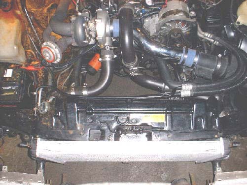
Notice pipes. Stock uppipe comes off turbo. 90* "U"
bend pipe that is cut in half is used for Intercooler inlet
and outlet. The two other 90* pipes are used for the two-piece
uppipe that goes to the throttle body.
 ic16-2.jpg
(no caption)
 ic25-2.jpg
That pipe is aluminized 2 1/2 exhaust tubing. I used 2 of these
mandrel bent 90's this one from the throttle body turning down,
and the one it is connected to turning over toward the outlet
of the Intercooler. I also had one 2 1/2" mandrel bent
U-shape pipe that I cut in half in the center of the "U".
One side is attached to the inlet of the Intercooler and the
other half is attached to the outlet of the Intercooler.
 ic3-2.jpg
This picture didn't turn out well, but the tag has been proven
many many times.
 ic13-2.jpg
(no caption)
 ic14-2.jpg
(no caption)
 ic15-2.jpg
You can see here where the inlet of the Intercooler goes through
the radiator support and you can see were it sits on the frame.
 ic11-2.jpg
Same as other but this is drivers side.
 ic12-2.jpg
This one shows the reducer hose from Precision
Turbo and the trimming I did to the inner fenderwell. Very
right of the picture is the air filter... plenty of room there.
 ic17-2.jpg
Nasty picture but you can see here the trimming done to the
passenger fenderwell and battery clearance
 ic18-2.jpg
Good picture of just how big this Intercooler is. See how I
fit the plate back in above it and cut the ends off the plate
to use for header support. This prevents the Intercooler from
having any side to side movement.
 ic2-2.jpg
This is on the drivers side were I trimmed the bumper bracket
back and used the tabs on the Intercooler to rest it on the
frame. No way its going to fall out
 ic20-2.jpg
Passenger side Intercooler tab resting on the frame.
 ic19-2.jpg
Showing were I cut the end of the original bracket off and fit
it back in. Notice where I split a piece of vacuum line and
glued it to the edge against the Intercooler.
 ic21-2.jpg
(no caption)
 ic1-2.jpg
(no caption)
 ic7-2.jpg
(YUCK) here you can notice that I'm not running the oil cooler
on the radiator right now. I did not find were it would be a
problem, it is just out because the radiator was leaking.
 ic5-2.jpg
(no caption)
 ic8-2.jpg
Close-up of Intercooler against top of radiator support notice
how far the top was cut back .. it opened the front of the radiator
support . it will have to be reinforced by welding spacers inside
it to keep the plate that holds the hood latch from flexing
or I ran four bolts all the way through with spacers in the
middle to tighten the top back up... worked just fine.
 ic26-2.jpg
the other end of the factory plate beside the Intercooler
 ic22-2.jpg
Good shot off the outlet side plumbing going to the throttle
body.
 ic24-2.jpg
(no caption)
 ic23-2.jpg
(no caption)
 ic6-2.jpg
The pipe right there happens to be my factory up pipe that was
cut to fit.
 ic4-2.jpg
Showing the back of the header panel were it needed cutting
behind passenger side high beam.
 header1-2.jpg
Again header cutting around high beam on drivers side.
 header2-2.jpg
This one is showing were after the install was done I cut the
plate that goes from the header panel to the radiator support.
This fills in the gap from the Intercooler up to keep some of
the air from going over the Intercooler instead of through it.
 header3-2.jpg
This is behind the high beam on drivers side. It is very tight
back there. Notice were I put the spring for the headlight bucket.
There is no side to side adjuster anymore, but with the spring
at the bottom and the adjuster at the top it holds the light
in place tight enough to set the side to side by hand and it
stays in place. You just have to make sure to mount the spring
far enough back to keep a good tension on it.
 ic10-2.jpg
This picture is with the headlight bucket in place. You get
a better idea of spring location and how it works.
 ic9-2.jpg
Can't forget to clearance the hood. This is not easily noticed
when people look under the hood. The hood seems to be very sturdy
still, and it can't be seen with hood closed. I'll make it prettier
when I start on body work and paint.
 ic28-2.jpg
Another shot of hood clearancing. Notice that it's basically
body line to body line on the hood
 ic27-2.jpg
|

 ic16-2.jpg
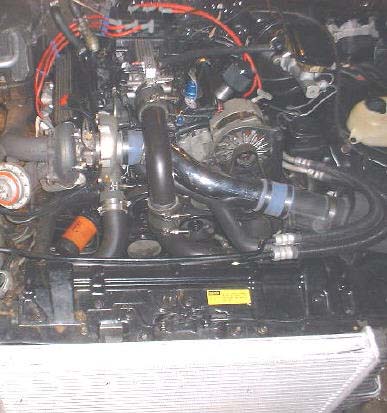 ic25-2.jpg
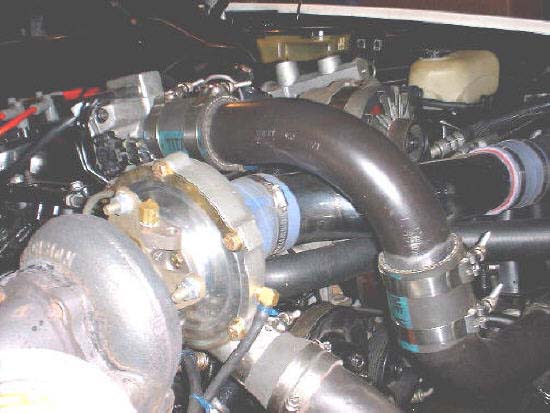 ic3-2.jpg
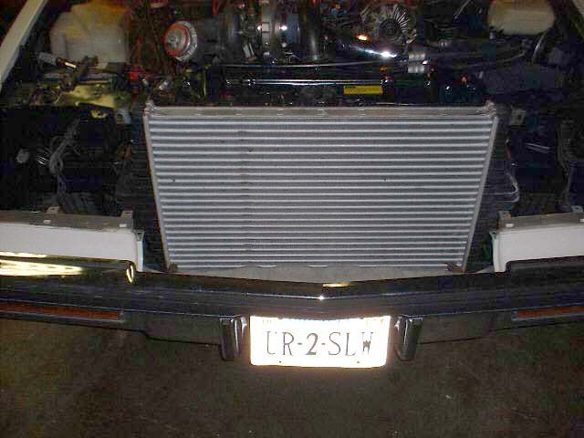 ic13-2.jpg
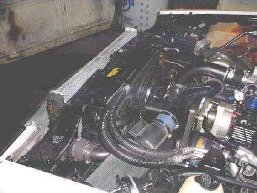 ic14-2.jpg
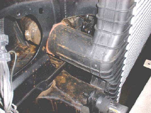 ic11-2.jpg
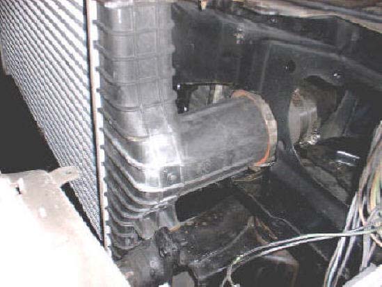 ic12-2.jpg
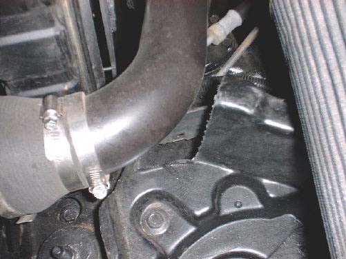 ic17-2.jpg
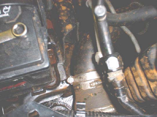 ic18-2.jpg
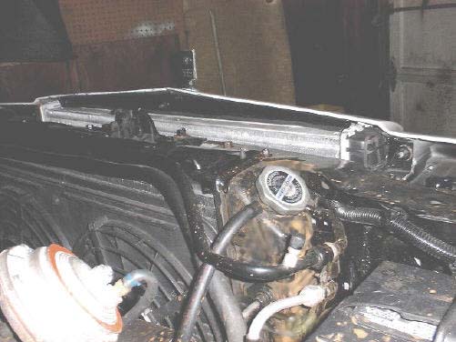 ic2-2.jpg
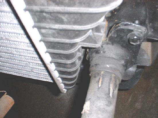 ic20-2.jpg
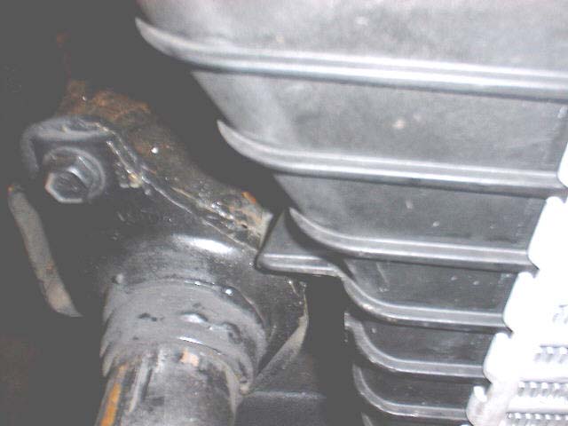 ic19-2.jpg
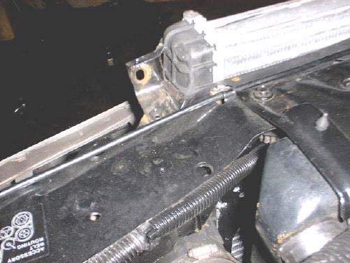 ic21-2.jpg
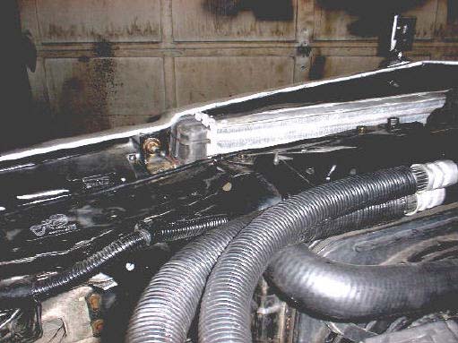 ic1-2.jpg
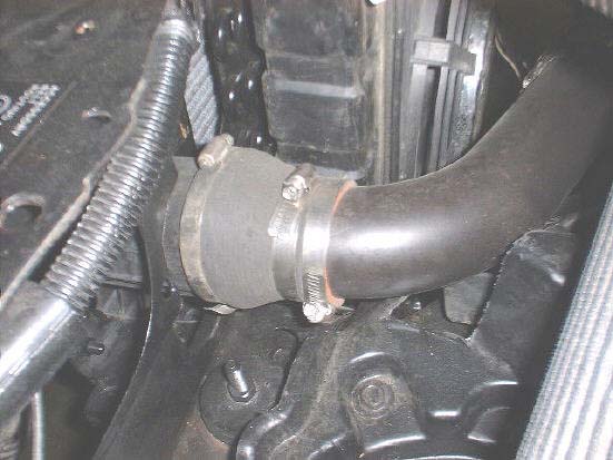 ic7-2.jpg
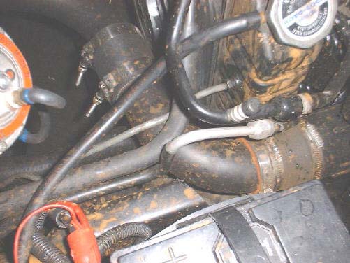 ic5-2.jpg
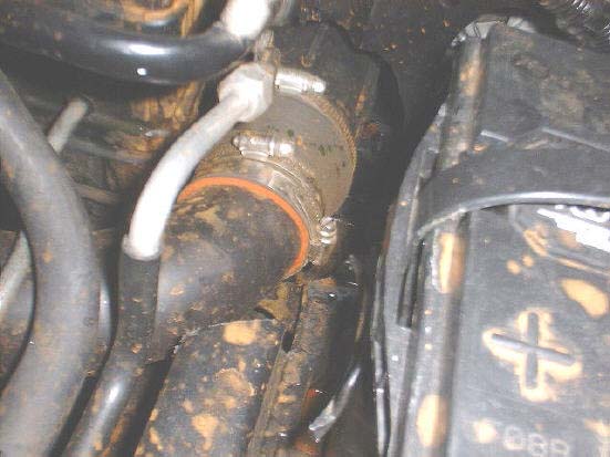 ic8-2.jpg
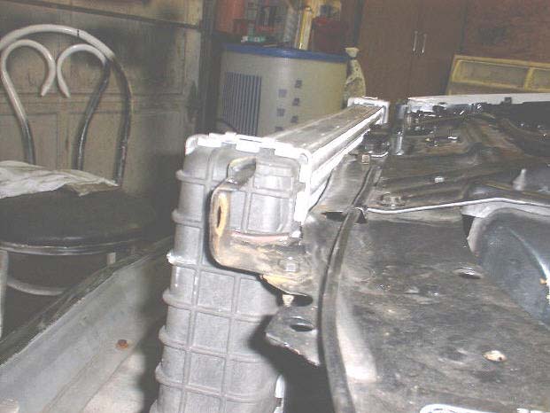 ic26-2.jpg
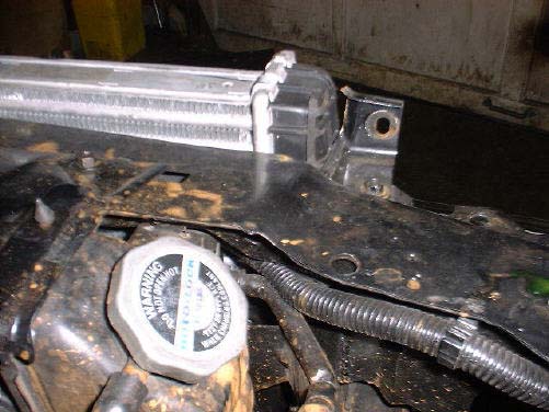 ic22-2.jpg
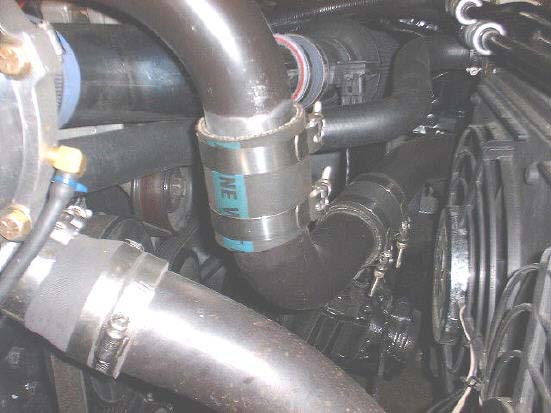 ic24-2.jpg
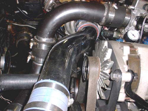 ic23-2.jpg
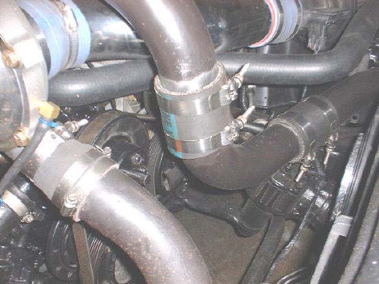 ic6-2.jpg
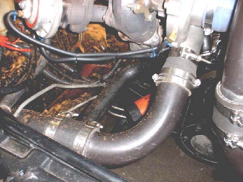 ic4-2.jpg
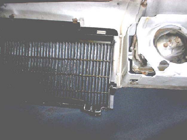 header1-2.jpg
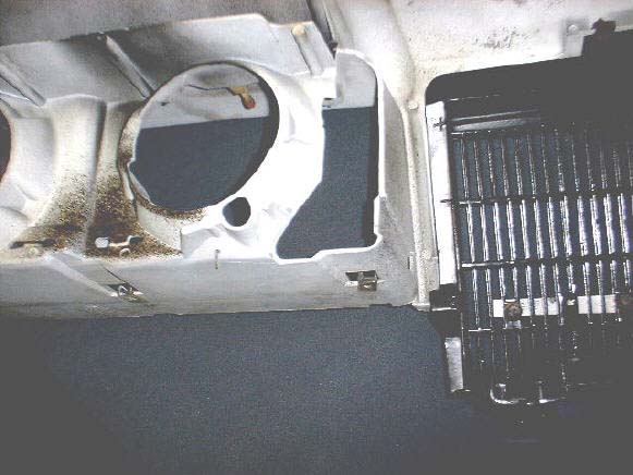 header2-2.jpg
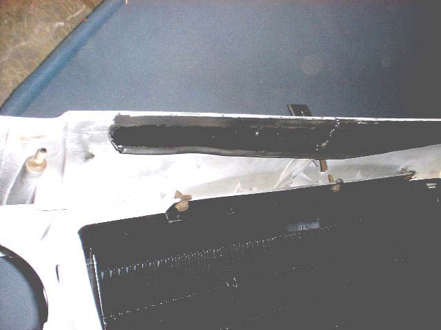 header3-2.jpg
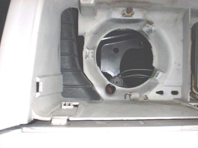 ic10-2.jpg
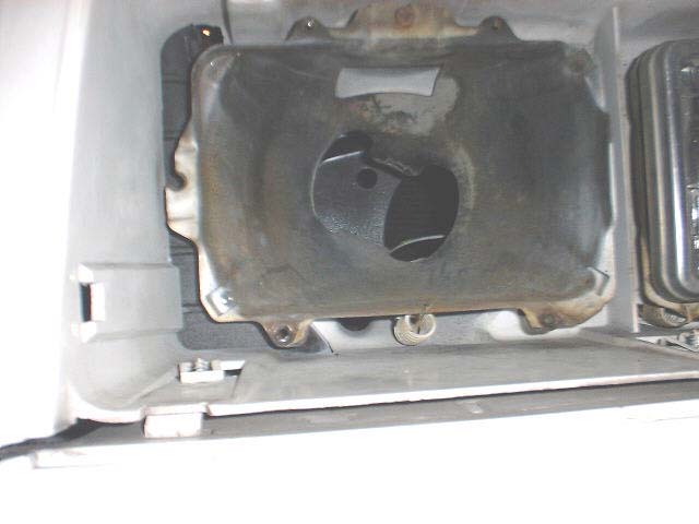 ic9-2.jpg
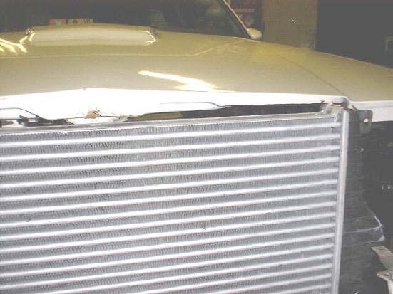 ic28-2.jpg
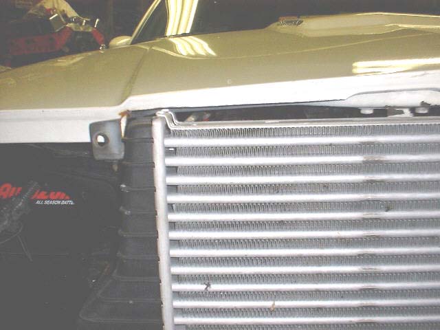 ic27-2.jpg