 Browsing the ol' internet, I saw several designs for compact loops.
I realized that I needed to use inductive loading to cram an 80m antenna into my 10m by 10m roof space. I found Cebik's thoughts and Pfeiffer's ideas on
loading quads informative.
See my variation of the compact
loop in the figure below.
Browsing the ol' internet, I saw several designs for compact loops.
I realized that I needed to use inductive loading to cram an 80m antenna into my 10m by 10m roof space. I found Cebik's thoughts and Pfeiffer's ideas on
loading quads informative.
See my variation of the compact
loop in the figure below. I feed it with a balanced line which goes to my big balun and then to the tuner. It tunes rather well on all bands including
1.9mhz- TOP BAND! The inductive loading shown is typical. Generally loaded loops will require
maybe 10 to 30 percent more copper wire than a full size loop. The "coils"
are supported by string, in this case used tennis racquet string, which was handy.
I feed it with a balanced line which goes to my big balun and then to the tuner. It tunes rather well on all bands including
1.9mhz- TOP BAND! The inductive loading shown is typical. Generally loaded loops will require
maybe 10 to 30 percent more copper wire than a full size loop. The "coils"
are supported by string, in this case used tennis racquet string, which was handy.
It is imperative that after initial stringing up, one must determine the frequency of resonance.
With the loop so close to my concrete roof impedance is unpredictable and resonance
was hard to find. It was determined "intuitively" as follows:
Values of swr are charted for frequencies from 3 to 30 mhz. You should note the dips in
swr as one goes from from 3 to 30 mhz and the spacing in mhz of the dips.
This "spacing" should be the fundamental resonant frequency.
For example if you see a dip at 20 then at 24.3 then the spacing- 4.3 will correspond to the fundamental 4.3 mhz which is too high for 80m. Your antenna is too short!
If too high just add more
wire, if too low, subtract. I would say a good rule of thumb would be 10 feet for 500khz.
80m. Add or subtract the wire to or from the loading sections.
 This article is dedicated to Frank G3JNO (SK) who once said that 160m was the "gentleman's band".
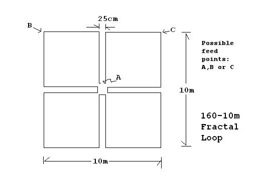
I updated my loop to a simple fractal design as of April 10, 2008. I used only one iteration. I ended up using only about 80 m of wire and may i just say that it is a unique antenna that will tume well even on 160m. I fed the loop at point A but I suspect that feeding at the corners, Points B or C will be better, particulalry for the higher bands.
I am not sure whether it can be called a resonant antenna but with the tokyo hi power hc-2000, it can be made to "resonate" quite well on all bands.
It is definitely worth investigatin as a compact antenna based on fractal theory. It might not be the best configuration, but is the easiest fractal type loop to put up.
 Mon
Mon