In recent years a new type of noise has been heard on the lower hf bands. Many years after the demise of the Russian woodpecker, we have been awaken by a new noise that many suspect as a jamming device aimed at a clandestine radio station or a special kind of radar.
So we break out the old oscilloscope and check the waveforms of the noise at certain receiver checkpoints.
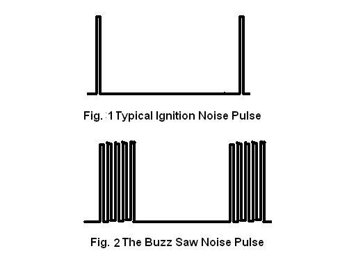
Fig.1 shows the typical ignition type noise pulse that most blankers in older radios are designed for. Fig. 2 shows the new "designer" pulse train that seems to be intended to put out the broadest possible signal. The pulse has a repeatition rate of about 43.19 Hz and one period is about 23 milliseconds. The pulse itself occupies only a fifth or so of the entire period. Remember how we like our cw envelopes shaped, with gentle slopes and not too sharp edges to avoid clicks on adjacent frequencies. This new noise wave are very sharp pulses that when used to modulate a carrier will certainly produce a very broad signal. Talk about super sized clicks!
An effective blanking pulse must cover the entire pulse train. The time constants of original blanker circuitry are just too fast to deal with the pulse train. So the aim would be to extend the blanking pulse to cover the entire train, or as much of it as is possible.
We tried several ideas and found the following to be the most effective.
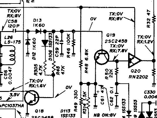
Figure 3
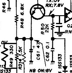
This is a typical noise blanker circuit of an old Icom radio, specifically, an IC-729. Others in the IC-72X series may have similar circuitry. A very high gain stage takes a sample of the received signal and feeds a voltage doubler. This is essentially a rectifier which converts the rf noise into dc pulses. Take note of the voltage doubler diodes d12 and d13 in the circuit of figure 3. Its output, a DC pulse corresponding to a noise pulse, drives q19. Q19 then draws base current from Q20 so that a positive blanking pulse is produced at its output. These pulses then reverse bias some signal diodes in the I.F. amp, thus blanking the noise.
Figure four shows the modification done to the existing circuit. A 100 ohm or so resistor was initially shunted across R49, to increase the gain of Q19. I found that Q19 produces a better shaped pulse with the increased gain. I tried using a short across R49 and things even got better! The lower end of R49 is connected to the noise blanker switch on the front panel. It is grounded to enable the blanker.
The collector of Q19 is shunted to ground with a .02 uf mylar capacitor, so that when Q19 conducts and then its drive removed, the voltage at its collector will rise slow enough to make Q20 conduct a little longer after the drive from Q19 is gone. This causes the pulse developed at the output of Q20 to to be extended long enough to blank the entire noise pulse train. The value of the capacitor I used should be a guide. You can either use your ear or a scope to check the effect of component change by monitoring the output of Q20. Using too little capacitance will not make the blanking pulse long enough and using too much might blank the signal too long, there will be no no signal heard from the speaker. hihi. >The resulting waveforms are shown in fig. 5.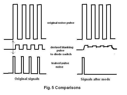
If done right, the blanker should quiet the buzz saw enough to sound just
like common ignition noise, or even quieter. In my case I experienced maybe
from an S-9 buzz saw reading to about an S-3 reading. And the band becomes quiet enough to make it bearable to hear the weak to medium strength desired signals. Of course sometimes the signal from the buzz saw is too strong, but I found this mod works well enough 70 to 80 percent of the time. When monitoring very strong stations , as is standard practice, we leave the nb off, so that audio will not be distorted when the blanker kicks in on voice peaks.
.
Mon DU1FV