Projective 2D Drawing System
Mohit Singhai, Arun Ramasamy
Dept. of Computer Science
SUNY, Stony Brook.
Email: {mohit,
aramasamy}@cs.sunysb.edu
Introduction:
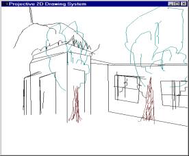
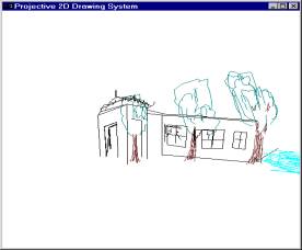
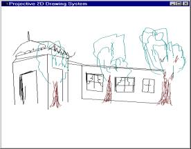
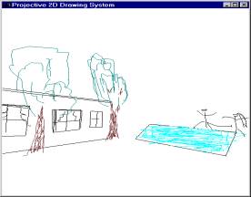
This project presents a new environment for perspective drawing. The idea is to use projective 2D representation of points, instead of conventional 3D methods, which renders the operations faster and provides just as much facility, as there is in conventional methods. We also provide an intuitive user interface, which helps the user to do freehand sketching and move around the 3D environment. The system supports basic 2D- sketching primitives. This project is inspired by the work of O.Tolba, J.Dorsey and L.McMillan, LCS, MIT where they describe a similar system to compose and render perspective scenes.
Projective 2D-Strokes:
In
conventional 2D- drawing systems, the points are represented with two values
along the primary coordinate axes. However, we can have alternative
representations of points, which can have Euclidean points as the subset. This
is apparent when we consider representing points using homogeneous coordinates,
and all points are of the form (x, y, w). All the points of form (x, y, 1)
represent the Euclidean subset. In Projective 2D drawing system we adapt this
representation and use a model where all the points are projected on a unit
sphere. It can easily noted that all points of the form l(x, y, w) represent a equivalent points on
different homogeneous planes. The Euclidean subset is obtained by picking l such that l(a, b, c) gets reduced to
the form (la, lb, 1). Since all the points in projective 2D
drawing system are supposed to lie on a unit sphere, we choose l such that a*a + b*b + c*c = 1.
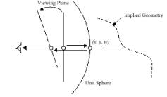
The
2D primitives drawn by the user are hence stored as a list of points projected
on the unit sphere. The unit sphere is defined about the viewer. Along with the
primitive attributes like color value associated are also stored. The system
enables the user to change his views and position, which results in the change
of projections on the sphere. This provides the apparent rotation or
translation of required of the system.
The Perspective Drawing System:
The
system provides the following main features:
1.Perspective
viewing and Guides
2.Shape Primitives
3.Manipulation of
primitives-translation and rotation
4.Save and upload files
contrasted using the system
Perspective viewing and
Guides:
The
view is defined by the position of the unit sphere, centered about the viewer
and the direction he is looking at. In general all the points that are
projected on the unit sphere are projected on the view plane, which is then
viewed by the user. The direction the user is looking at changes, then the
position of the image plane changes.
The
system also provides vanishing points and grid lines as intuitive guides. The
vanishing points define directions along the unit sphere from the user. At any
point of time the system defines two active vanishing points, which actually
determine the change of view. They can also be looked at as the projections of
parallel lines on the unit sphere, which tend to converge at infinity along
that direction.
The
perspective grid lines provide an interface for the user to have a ‘feel’ of
the environment. Grid lines also tend to change their directions like the
vanishing points as the user view changes.
Shape Primitives:
The
system defines a set of primitives, which the user uses to generate a more
complicated environment. The basic primitives available are
1.Pencil
2.Lines
3.Circles
4.Polygons
In
general based upon the geometry of the primitive being drawn the required
amount of information is stored. For example if the user draws with pencil all
the points projected on the unit sphere are stored, where as when a circle is
drawn only the center, radius and the axis of rotation in 3D is stored.
Manipulation of shape primitives:
The
primitives can be manipulated in such a way that they generate an apparent
motion effect as desired by the user.
Apparent
translation is achieved through usage of homographic matrices. The mappings
from one position to another are achieved using the mappings of the projective
planes. The normal of the plane can be calculated from the currently active
vanishing points and is used in the transformations. The user, while
translating the object provides information as to the direction of the
translation and magnitude of the motion along that direction. These are used to
calculate the transformation of the image, which is then re-projected on the
unit sphere to get the transformed image.
Apparent rotation is also achieved through
homographic transformation of points. The user specifies the direction of
rotation and the pivot. The user can then drag the object along that direction
so that the magnitude of the rotation angle is obtained. This information is
used again in transforming the current view to the changed one, and is
projected on the unit sphere.
When the user changes the angle of view or the
position of the camera, the vanishing points, which are currently active
changes, which brings about the results described earlier.
The
user can also change the color of the object he is drawing using the interface.
Implementation:
The
implementation was mainly concerned with design of a data structure for storage
of the points, and mathematical calculations involving projections of the
points on the unit sphere. Each object defined by the user-pencil, circle etc-
was stored as a list of points containing enough information to regenerate
them. All these objects were then stored in a list of objects, which were to be
projected on the unit sphere. This gave the system capability to ‘undo’
whatever the user has done, if he wants, by removing links from the list.
The
projection of points on the sphere was implemented solving quadratic equations,
which come naturally associated with the problems involving sphere-line
intersections.
|
|
The
system also enables the user to store files, which can then be read into the
data structure for projection. The system files have a specific format
pertaining to the system, and are read into the data structures when the file
is loaded.
Conclusion:
The
project is completed as per the requirements. However, features like shadows
and silhouettes would add a more realistic effect to the environment. The
project can be used in areas like architecture and designing basic geometry of
objects in a 3D environment.
Reference:
[1] Tolba, O., J. Dorsey, and L. McMillan, Sketching with Projective 2D
Strokes, UIST '99: Proceedings of the 12th Annual ACM Symposium
on User Interface Software & Technology, Asheville, North Carolina,
November 7-10, 1999, CHI Letters, Vol.1, Issue 1, pp. 149-157.
[2] Tolba, O., J. Dorsey, and L. McMillan, Projective 2D Drawing system,
I3D-2001.