Foreword: The main purpose of this FAQ is to provide a very basic understanding of automotive electronics, answer some basic questions, and hopefully provide you with further interests in learning more. I have used a basic lighting requirement as an example but the concepts are universal for all the electrical circuits..
How do the electronics work in my car?
That's a very common question among Mitsubishi owners. As you work on, upgrade or modify your Mitsubishi 4x4, the question is bound to come up. To answer this, you first need a basic understanding of electricity.
Electricity is simply the movement of electrons in a medium that conducts electricity (usually copper wire). This movement of electrons creates energy which we can harness for our use. Now, this isn't meant to be a thesis paper on electronics, so I'll leave it at that.
So, electricity is the movement of electrons... so how does this work for me in my car?
There are several key elements to know about electricity....
Voltage, Resistance, Current, and Power
The easiest way to help someone understand electricity is to think of a water system where water flows through pipes. Flow is controlled by valves. There is a system pressure and a specific rate or speed at which the water flows.
Voltage is analagous to the pressure forcing the water through. In electrical terms, it's known as "potential" and you'll sometimes hear the term "voltage potential"..
Current: Regardless of the voltage however, if a water valve isn't opened, or the pipe is clogged, water flow can be controlled. The amount of electrical flow is the current and it is measured in amps.

Resistance is kind of like an obstruction to the water flow. Take for example a water mill. Like the water example, we can use resistance in an electrical circuit to harness the power of electricity.
Wattage is a measure of the amount of power there is in a circuit. If you think of a water mill, the power the water has is defined by a couple of factors... the amount of water pressure (Voltage) and much water flows (Current). Similarly in electronics the Voltage (pressure) and the Current (water flow) define the amount of power a circuit has.
If this is still unclear, don't worry too much about it. As you read further it should help clear up any confussion you might have.
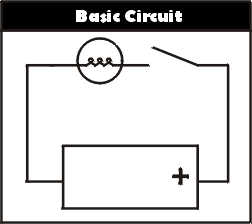
Here is a diagram of a simple electrical circuit.
The square box is a battery with a + sign showing the positive side of the battery. The round circle represents a lamp and the diagonal line represents a switch.
If the switch closes, then electrical current will flow from the positive side of the battery though the switch, through the light, and finally back to the other side of the battery (negative side).
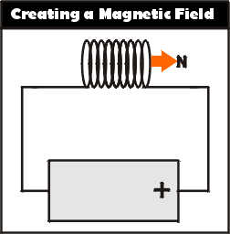
Creating a Magnetic Field
One of the cool things you can do with electricity is create a magnetic field. If you take the wire that the electricity runs through and coil it in a bunch of loops one after another, it creates a magnetic field when electricity runs through it.
The diagram on the left shows this although the polarity on the magnetic filed may not be correct
Note: For you electronic geniuses out there... I
know, the field is backwards. I wanted to see if
you were all paying attention.
Now by creating this magnetic field, you can move metallic objects.
If you can move metalic objects by merely turning on a switch, you can use electricity to do something that would normally require a human to do physically.
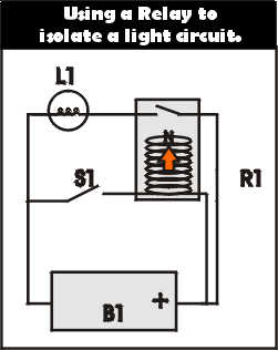
Using a Relay
One example of this is in a relay. A relay is nothing more than an application using this electromagnetic field. Note the box "R1" in the diagram on the right
When you close the switch (S1) a magnetic field is created in the electromagnet in R1. In turn, it pulls the switch (above it) closed. This allows current to flow from the positive side of the battery (B1), throught the light (L1), turning it on.
As a side note, current also flows through the relay's coil, through S1 and back to the battery.
Why Use a Relay?
Now why go through all this trouble? Why not just put a switch there and be done with it? Well, in one word, Isolation. You want to isolate this electrical circuit from other circuits. In an automotive light application, you draw a lot of power (55 watt's minimum, and much more with brighter bulbs). If there's a problem with this circuit, you don't want it destroying the rest of your electrical system.
By using the relay you physically isolate it from your other circuits.
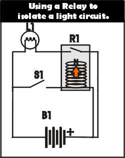
The final diagram on the right shows the same circuit but with the actual battery (B1), switch (S1), and light (L1) Symbols. The relay symbol would be similar but not exactly like the one of the right.
I hope I have given you a basic understanding.
For further questions, please contact me, or do a search for Electronic Theory using Google, Yahoo, Alta Vista or other popular internet search engine.
