

the interior fan, turn signals going on and off... the
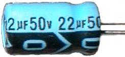
An electrolytic Capacitor.
Which capacitor to choose? There are a lot of different types out there - some large, some small, some really accurate, some "cleaner" for low noise applications, etc. For power supply filtering, electrolytics are almost always used. Power supplies generally require a large capacitor to absorb spikes and dips. You can't afford not to have a steady power supply line inside of a computer - the microcontroller might act erratically or reboot. Elecrolytics are chosen because they provide a lot of filtering for their small size. They are also very cheap.
The Problem
Electrolytic capacitors do have a downside though. They tend to leak with age when exposed to head and many power cycles. The electrolyte that leaks out is very harmful to PC boards. It can actually eat the copper traces eventually making a short on the board. When that happens, the ECU will either stop working altogether, or act very erratically. As the capacitor leaks, it will also lose its filtering properties, allowing possibly harmful spikes into the ECU.
Signs of Impending Doom
Luckily, there are usually some warning signs that your ECU is on its way out.
1) A rapid clicking or chattering from under the dash. Usually accompanied with the engine stalling or loosing power during the noise. This is the microcontroller going into reset over and over and over again due to a bad power supply. Every time it resets, it will turn the fuel pump relay on and off. This could also be a bad fuel pump relay, but not usually.
2) An usual smell that seems to come from the center console. Especially if it semll like rotten seafood. Consider that it could also be your heater fan motor, unless accompanied with a power loss or stalling.
3) You car is older than seven years and sees a lot of extreme temprature transitions.
If you experience either of the first two problems above, act on them as soon as possible. Even though your car may still be drivable, the longer you let the problem go, the more likely you will end up with a hole in your ECU's PC board or with several blown components on the board. Then you will have to dig up a unit in the junkyard or buy a new one from Mitsubishi for $1100.
1) Purchase the Replacement Capacitors.
Unfortunately the particular capacitors you need can't be found at Radio Shack. They can be found at Digi-Key, however.
+ 47uF @ 50V (Digi-Key # P5570-ND
+ 22uF @ 50V (Digi-Key # P5567-ND)
+ 100uF @ 25V (Digi-Key # P5540-ND)
By the way, in general you can "up" either the voltage rating or the capacitance of the capacitor in a power supply application if you wish
2) Gather Supplies
Although the instructions below are written for using copper solder braid and a solder sucker, we recommend using a professional desoldering station with its own air supply. A solder sucker and solder braid will do the job, but are much slower and not as accurate as the real thing. Make sure you have a good soldering iron with a large tip. You are also going to need some solder. (Make sure it's rated for electronic use. 60/40 Solder is
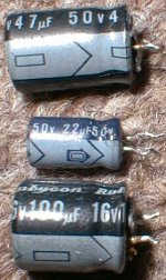
The 3 capacitors you'll need.
3) Remove the ECU.
Solder Sucker and Desoldering Braid.
4) Remove the PC board from the case.
Now would be a good time to put a grounding strap on your wrist, if you have one. Take four scres out of the side of the case. Keep in mind that they might be incredibly tight. At lease one usually is. Consider using a flat-blade Screwdriver very carefully on the tough ones to get better torque. There are also four screws in the corners of the PC board itself. The same rule applies to those screws as you try to remove them.
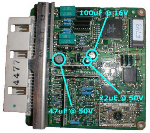
5) Locate the Capacitors
Figure 4 (click to enlarge) shows the positions of the capacitors and their values. You might want to inspect them for any sign of a leak or maybe a smoke trace if you've had a problem.
6) Add Solder to the Capacitors
Why do we add solder when we will just be sucking it away later? When the boards were wave soldered at the production factory, solder will attach to the capacitor leads on both the top side and the bottom side of the thru-hole copper pad. It is possible that there is little or no solder in the hole between the top surface and the bottom surface. By adding solder back in, we assure ourselves there will be enough solder to conduct heat from the bottom of the board to the top
The 3 Capacitors
Adding Solder
7) Bend the Capacitor Leads
Now would be a good time to straighten out all the capacitor leads. Figure 6 (click to enlarge) shows this being done with a tweezer while heat is applied with a soldering iron. This will make it easier to both solder suck and remove the capacitors later.
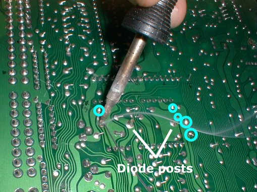
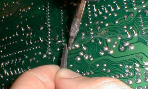
8) Sucking the Solder
Figure 7 (click to enlarge) shows the relatively mundane task of sucking out the solder. Make certain that the solder is nice and hot and is flowing well before you fir the trigger of the sucker. If you do it right, the solder will be sucked off the top later of the board as well.
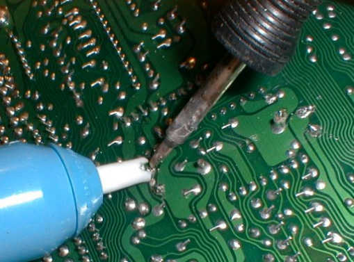
9) Clean the Pads.
The hand-held manual solder sucker rarely gets all of the solder. Most of the time, you have to clean up after it. Figure 8 (click to enlarge) shows a copper solder braid being used to sop up all of the residual solder to ensure a clean pull of the capacitor.
10 Pry out the Capacitors.
Using a tweezer, or small screwdriver, carefully pry out the capacitors. If you encounter some resistance and it doesn't feel "right", you might want to go back and reclean the pads, or go as fare as adding back more solder and beginning the whole process again. remember that you don't want to "pop" one of the thru-hole pads, or you will be doing some repair. Figure 9 (click to enlarge) shows the 47uF capacitor being removed.
11) A Look at the Naked Board.
Now that the capacitors are off, you should give them a good sniff. If any of them smell at all like rotten seafood, they are leaking. be sure to pay attention to the area of the board underneath a leaking capacitor. for example, the ECU in Figure 10 (click to enlarge) had the faintest odor of rotten seafood from the 47uF capacitor. Notice that the bottom hole pad shows some darkness around the lower pad. It is the beginning of the oxidation of the copper pad. This ECU was caught just in time. Another thing that should be noticed in Figure 10 is the marked polarity of the hole pads. Inserting a capacitor "backwards" can lead to an explosion.
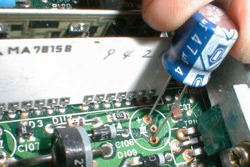
12 Install the Capacitors
It is EXTREMELY IMPORTANT that you install the capacitors with the correct polarity. If you do not, the capacitors might explode, doing who knows what damage to the board. In Figure 11, on the capacitor, you can clearly see the negative sign inside of the arrow which points to the lead that is negative. Note in this picture that the hole on the ECU PC board which the negative lead is going into is NOT marked with a plus sign. Only the possitive hole is marked on the ECU PC board. Be sure to put the negative lead in the opposite hole from the positive one. After you push the capacitor all the way down, take the leads on the bottom and bend them outward as they were from the factory. This will hold them in place for soldering.
13 Solder the Capacitors
Downhill from here on out. Solder each of the capacitors as in Figure 12. Be sure to trim off the leads so there isn't a short.
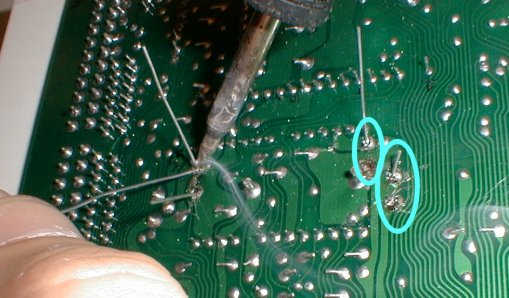
14 Cleanup
Almost done! Check out the soldering job using a magnifying glass. Often the solder will splatter a bit when using the solder sucker and solder braid. Usa a fine tweezer as in Figure 13 to remove each small piece of solder or metal the represents a possible short. Then screw the PC board down onto the bottom of the ECU case, put the cover on the ECU case, and you are ready to go!!
Bending Leads
Sucking the Solder

Cleaning the pads

Popping the Capacitor
The board without Capacitors.
Capacitor Polarity
Soldering the Capacitors

Removing solder blobs.
1) Aside from minor changes, this article was copied in its entirety from the Technomotive website. http://www.tmo.com/howto/ecu1g/caps.htm
2) No warrantee nor claims are made by this article. It is the sole responsibility of the vehicle owner to verify that these proceedures will have no adverse affects on their vehicle. Neither the Mitsubishi Four Wheel Drive Club of North America nor Technomotive can be held liable for any problems or situations caused by following these directions.
