 |
Overview
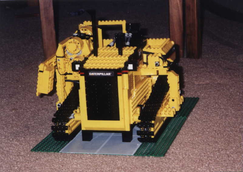
I saw a few of these one day laying down a
gas pipe that streched across farm land.
Before then I had never seen any, and naturally they looked very
strange. That was back before I really made any sort of LEGO models; I
had
always planned on one day doing some sort of pipelayer using the RCX.
Finally, I got around to making it, as a semi-realistic model, and
here is the result. This model is completely motorized, save for one
pneumatic switch to operate the counterweight. It took me a few weeks
at the minimum to make and finalize.
|
 |
Finding
Dimensions
This is a diagram I found off of
the Chrysis Construction page. This was very helpful in the
planning stage. On their website below this picture were given the
actual dimensions, as they corresponded to the letters in the diagram.
Using those numbers I was able to find an appropriate scale and convert
my new found inch measurements to the relative equivalent of Lego
studs. |
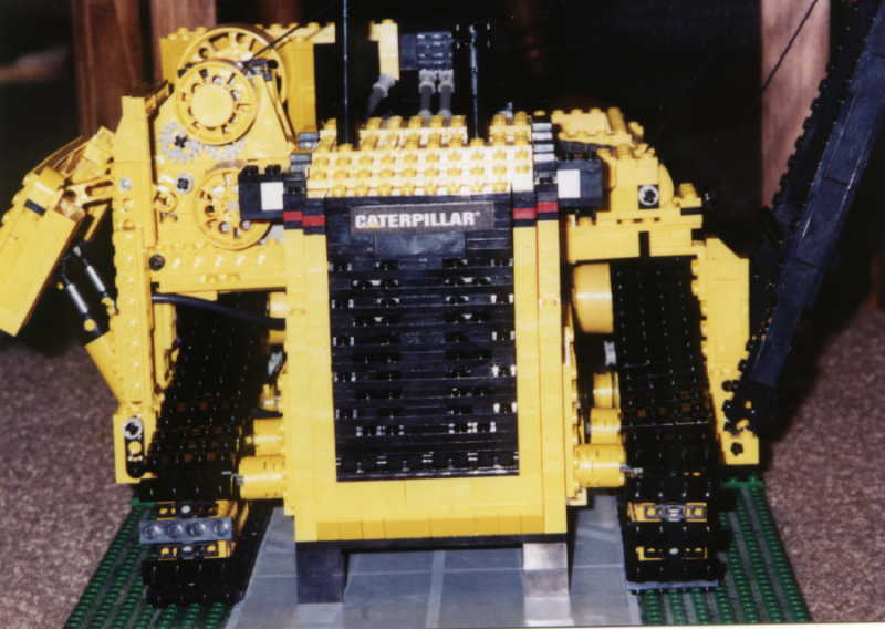 |
A Little more
on the features....
Here's a shot of the front of my
version of the 561M. To the right you have the boom, which I chose to
build in black because of my lack of yellow parts after constructing
the body and also I think it improves the overall look. Just left of
the boom is the winch that raises and lowers the lift cable. To the
left of the picture is the hoist winch and the pneumatically controled
counterweight. If you've noticed the black 2x2's at the base of the
model, those were just for support during the picture taking process.
The tracks proved to be pretty rigid, and did most of the work in
keeping the model on the ground when lifting. And, with 5 motors and 2
battery boxes inside, the model was heavy enough that it stayed firmly
planted whenever lifting things. |
 |
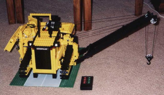
This picture is a shot of
the back, where you can see the boom partially extended. The chain seen
by the cab is for the winch. In the back, near the bottom. There is a
door that pulls down to reveal one of the small 9V battery boxes. This
one is used to run the pneumatic pump. Inside there is a cut-off
switch, which I made using a small pneumatic cylinder and a polarity swtich. This helped in controlling the model,
since I didn't have to worry about turning the pump on and off. |
| Electrical
Specs: As
I mentioned before, this model contains 5 mini motors. Listed here are
their functions:
1.) Left drive motor 2.) Right drive motor 3.) Hoist winch 4.) Main cable winch 5.) Pump motor Two small 9V battery boxes were used in this model, for very specific reasons. While it creates the hassle of having to turn 2 boxes on and off instead of just the one, I was able to reach and snake the electrical wires to where they needed to be with relative ease. But the main reason for this setup deals with the pump. Since I knew I was going to use a cut-off switch, I had to find another way to keep the main motors powered while being able to switch the pump on and off with the polarity switch. There are other ways of doing this than what I did, but seeing as space permitted I decided to go this route. It also took a little strain off the main box, since it didn't have to power the 5th motor. As far as the pneumatic system is concerned, I used 1 small cylinder, 2 large ones, and a small pump. The two large cylinders were used for swinging out the couterweight. While this was highly unnecessary to use 2, as one would've done the job just fine, I chose to use another one for cosmetic reasons. The small cylinder, as mentioned before, is used for the cut-off switch that turns off the pump motor when the pressure in the lines gets to be too much. The small pump is attached to the fifth motor. Because of how little this model demanded in that respect, it proved to do the job in supplying the needed air. The counterweight was operated via the switch located near the operator's seat. Because of the limitations of Lego cylinders, the only two positions the counterweight mechanism could be held at were all the way in or fully extended. |
|
 |
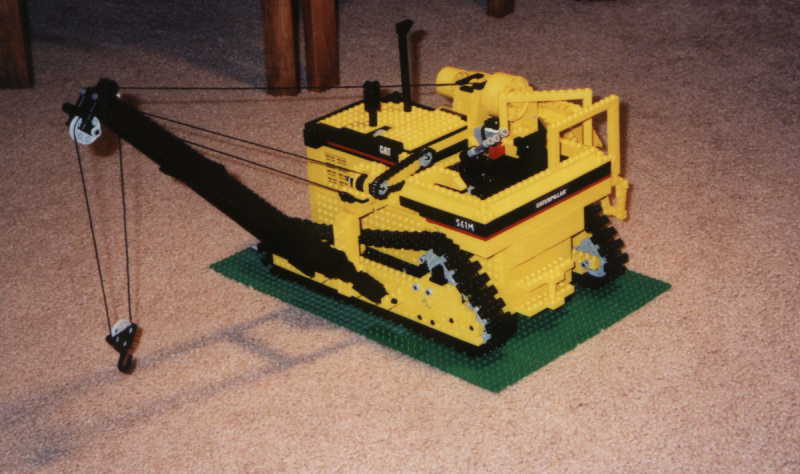
Taken
Down Here's
a picture of what I think the pipe layer would look like when it's
being transported. I removed the boom (not pictured) and took in the
cable. The counterweights are all brought in, and could be removed,
though I thought this to be unnecessary for my model. At this point it
could drive to a nearyby site or be loaded into a truck. I had some fun
just driving it around, though it went very slow due to the gear reduction. At a 1:120
ratio, it moved at best at a slow crawl. However, the tracks did what I
needed them to do; they were able to supported the full weight of the
model without need of the black supports and move it without any
problems. This was the first model that used a lot of tread links, and
I decided to put on black 1x4 plates on every other link to add to the
overall appearance. Plus, I didn't think the standard treads were wide
enough for this scale.
|
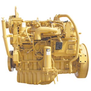 |
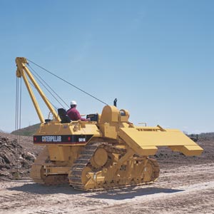
The
Real Thing This
is a side shot of a Cat 3126B HEUI engine, this one taken from a 561N
Pipe Layer. The 561M has a very similar six cylinder turbocharged
diesel engine.
|
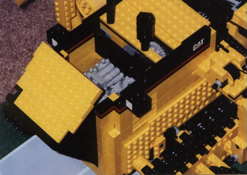 |
A
Bad Shot of My Rendition... The
front hood of the pipe layer hinges down to reveal the 6 cylinder
engine. It's driven by one of the drive motors, located nearby. Also in
the engine compartment is access to the second 9V battery box.
This one is in charge of powering 4 of the 5 motors, all operated
remotely by utilizing my rc unit from HiTechnic Products.
|
 |
In this last picture, you
can see a lot of everything. The only thing really left to cover is the
counterweight. Attached to the swing arm which moved it all in and out,
I had axels projecting out on either side. This made it so I could
slide on "weights" that I made and complete the look. While they have
relatively no weight, and don't really aid the model in keeping
balance, I thought I should keep this feature, even if just for looks. |
![]()
 © 1997-06 Contact
me
© 1997-06 Contact
me
 CLICK
HERE to go back to my main page.
CLICK
HERE to go back to my main page.