Electronics Project
1. Feeback control circuit
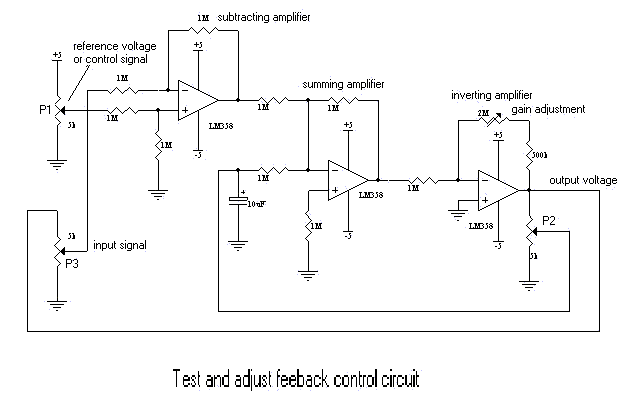
The following diagram shown the feeback control circuit. It is consist of subtracting,
summing and inverting amplifiers circuit. The subtracting amplifiers will generate
deferential voltage of signal input and reference/control signal voltage. The deferential
voltage will add to summing amplifier and amplifier by inverting amplifier until the
deferential voltage is zero. The feeback loop from potention-meter (P2) to summing
amplifier maintain the equivalent point of output voltage (where deferential voltage = 0).

The setting point of process control set by the potention-meter P1. Potention-meter P3 used
(act as external loop of simple process control)to test and adjust the circuit.
As an example:
Set the potention-meter P1 to 2.0 Volt. Then adjust the potention-meter P3 at the center
poit. Adjust the potention-meter P2 until feeback voltage of center point of potention-meter
P3 equal to reference voltage of potention-meter P1 (2 volt). Now, if you adjust the
potention-meter P3, the feeback voltage of potention-meter P3 amost not change (2 volt)
but the output voltage of inverting amplifier (supply voltage of P3) changed. The output
voltage may change from 2 volt to saturated voltage (maximum less than 5 volt due to offset
of voltage LM358). You can change supply voltage such as +12V and -12V to LM358 to test the circuit.
2. DC Motor Control Circuit
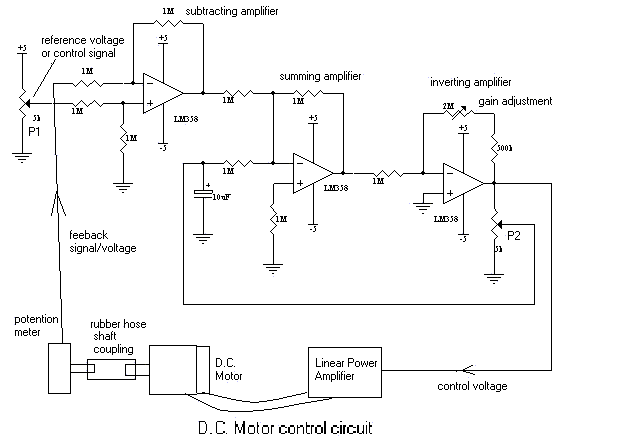
The above circuit had been applied to control the dc motor as shown on following diagram.

You may need to adjust the inverting amplifier gain to prevent oscilation of motor. The
motor will turn the potention meter until no voltage different between reference voltage
and feeback voltage (ideally is zero but pratically may not be which also depend on
application, motor). The circuit may no be suitable for slow respond of process control
such as temperature control and so on. I am not sure whether this circuit can be use for
other process control application. Normally, good and accurate process control system use
PID circuit for controlling. I am not familiar with this type of control which need integral
the process time respond and so on. My circuit design may not be good solution for process
control. Here, I only provided as another alternative reference who may think it is useful.
When you turn the potention meter P1 the motor will also turn accordingly until the feeback
signal of potention meter same with reference voltage (ideally). I had test this circuit 2-3
year ago. I am not sure the perfomance of this circuit. If you has any comment on this circuit
welcome email to me. See the linear power amplifier circuit at here:Power Amplifier Schematic
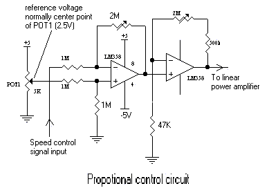
If you want the simple bidirection speed control of DC motor. The simple propotional control
circuit can be used as shown as following.

email: [email protected]


