If you have little or no knowledge of Spline Cage Modeling & Surface Tools I highly recommend the beginners tutorial on this subject.

In the front Viewport:

Step 1: When I model anatomy I always use a reference picture. Since this tutorial is about modeling an arm using Splines & Surface Tools I will show you a convenient way of doing it. First thing I always do is put the size of the image in the name of my reference picture. For instance the name of my reference picture for this tutorial is Arm621by119.jpg. This way, when I create a plane to apply the picture to, I know the exact size to make it. The reference picture is here at the top. You will need to copy this picture and save it to your computer so you can follow along.

Step 2: Now create a plane for the reference picture and apply the material. Make sure you have a shaded viewport and have the "show map in viewport" button selected in the material editor.
Step 3: We'll begin with going to create, shapes then circle. After you create the first circle click the rotate button next to your 3d snap tool as shown here. This will help you rotate your circle accurately. We are going to place a circle at each point where the elevation changes in the arm. For the sake of this tutorial I recommend you make six copies and position them like shown here. To make your life simple, rotate the first circle and then copy them over.
Step 4: Select each circle and modify the radius to match the height of the arm. You can either do this by accessing the Radius parameter in the modify panel or by using the scale tool.
Step 5: Go ahead and change the viewport to "wire frame" only and look at your progress in the perspective viewport. Your results should look similar to mine. If it doesn't, put away the tutorial your doing and start at Step 1.
Select the first circle. Right click the highlighted gray area that reads "circle" and collapse it to an editable spline. Now scroll down the modifiers panel and select the "attach multiple" button. You should get a screen like this. Just highlight them all and continue. If you cant find the "attach mult" button, simply attach them one by one. When you have some more free time I highly suggest learning all the "attach" options.
Step 6: Now we will attempt to create a Spline Cage to apply our surface to. In the sub-object level select Vertex. Now scroll down the modifier panel and locate the button that reads "Create Line" then select it. To assist us with locking our lines to the vertex we'll need to select the 3d snap tool (3d because our cage is essentially 3d).

Step 7: Now if you have done everything right, meaning you've made sure to lock the snaps to the vertex, you should get the cross hair over any vertex you run over. In the front viewport attach them to verticies from right to left straight across like I've done here. Then do the bottom the same way.
Step 8: In the top viewport do the same to the verticies that have not yet been connected. It's good, if possible, to connect your splines this way. It is also possible to do it in a perspective viewport, but you always run the risk of crossing over and connecting to a vertex that isn't the one you wanted to snap to.
Step 9: When you're finished creating all the lines. Click the "create line" button again to turn it off. Otherwise everywhere you will click on the screen will make a line. Which is very frustrating. So always remember to turn it off if you turn it on. Now region select all of the verticies in your cage. Right-click just one of them and you should get a menu that looks like this. Here we will select and change all of the verticies into Bezier Corners.
Step 10: Go to the main object level and make a "reference" copy of your Spline cage and bring it directly below the original in the front viewport.

Step 11: With the reference copy selected add a surface modifier to it. After you apply the surface, your model should look like a sectioned Kilbasa. To get rid of that sausage look, just check the box that reads "remove interior patches". To give an explanation on what's happening here: the surface modifier is creating a skin between any hole that has 3 to 4 verticies. Each circle has four verticies. So not only will you get patches on the outside, where we want them. You will also get them in the inside, where we don't want them. By selecting "remove interior" it will stop any surface from existing inside a model. Now incase you have problems seeing the surface, or you model looks funny. Try checking the "flip normals" box. If you cant see a portion of the surface try increasing the "threshold" slightly. Your attempt should look similar to mine here. If not. Fry up some Spam and try again later.
Step 12: Select the original cage. Any changes you make to the original should transfer over to the reference copy with the skin. This is a good modeling habit to follow. This will allow you to pay attention to both the Spline Cage and the Surface at the same time. Region select vertex by vertex and adjust the bezier handles so the curvature of our Spline follows the curvature of our reference picture.


While your adjusting your bezier (you gotta love that name) handles you may come across a situation like this. In this example, your bezier handles are coincedented with the verticies. There's two ways you can handle this.
1.) Zoom in real close and drag them out one by one with your mouse button.
2.) Right click it then change it to a "corner" type of vertex. Then right-click it again and change it back to bezier corner. If you do this, please remember you lose all the original curvature in all the viewports.
Step 13: As you're going from vertex to vertex you will come across this portion of the reference picture. You'll also find it near impossible to adjust the bezier handles to match the quick changes in curvature. What we need to do is create two new sections. So we can match the indention correctly.
Step 14: Go to the sub-object level and select "segment". We need to prepare our Spline cage for two new sections. Create two verticies on the segment at the bottom of the arm where the indentions go up. Then make two more even with those on the top segment.
While you are dong this, notice in your reference model you have lost a certain part of your skin. This is because you've created more than 4 verticies in that section.
Step 15: In the top viewport. Now add 4 more verticies where I have the red circles. It is a good idea to line them up with the new verticies you added in the front viewport.
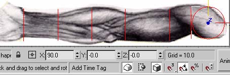
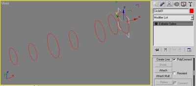
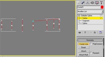
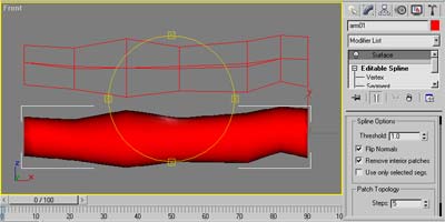
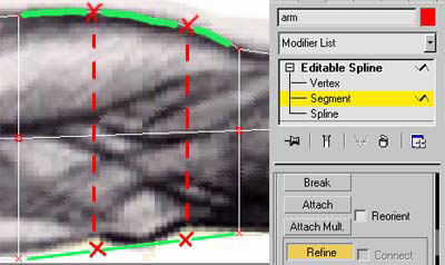
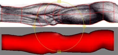
Step 16: In the front viewport create a new circle. Rotate it like we did at the beginning of this tutorial. Line it up vertically with the new set of verticies you've just created. 
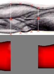
Make a copy of that circle and slide it over even with the second row of verticies you've just created. Notice how the verticies on the circles conveniently match up with the new verticies you've just created. We did this for a reason. 
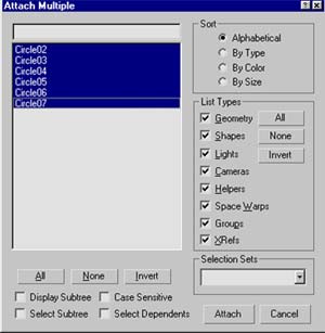
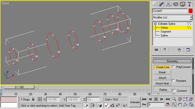
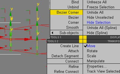
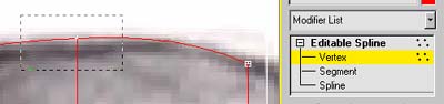
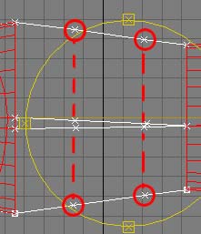
Select the spline cage and attach the two new circles. In the front viewport region select the top left new vertex. In your region selection you should grab one vertex from the circle and the top left new vertex from the cage. Now click fuse. Do this with each vertex you added. As you do this you'll see that you get your surface back.

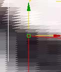
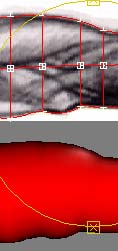
Be careful while your region selecting. You don't want a vertex included in your fuse that you don't want. So to make this easy do the top and bottom two in the front viewport. Then do the remainder in the top viewport.

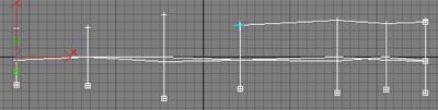
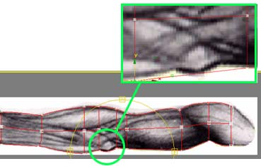
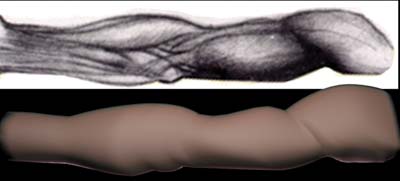
After you get your surface back, it may be a good idea to rotate around your model just to make sure everything looks ok. Something that is very common when your adding new lines and sections is that your surface flips! 
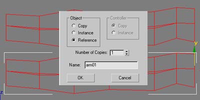
So if your model looks strange. Re-select the reference model. Go to the surface modifier and check the "flip normal" box again. This is very common. Sometimes it gets even worse than that and you may have to decrease or increase the "threshold". In some cases you may even have to go back to your cage and remove a few lines or add a few more verticies.

Step 17: Now do the final touch ups. Here I adjusted the curvature of the circles to go with the flow of the forearm. Remember, here we only have the front reference picture. If you notice in the top viewport your arm may look funky. To correct this you may want a "top reference" picture to work by. Or just use your artistic eye.
Final: If all went well you should come out with something similar to this. This modeling technique takes some time to get used to. Once you do, you'll find it so much faster than box modeling. Not to mention more accurate when it comes to organic shapes.
1
Hosted by www.Geocities.ws