BEGINNERS GUIDE TO SPLINE CAGE MODELING WITH SURFACE TOOLS.
|
BEGINNERS GUIDE TO SPLINE CAGE MODELING WITH SURFACE TOOLS. |
|||
|
|||
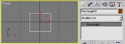
| Step 1: First goto shapes and create a square. Now place your mouse pointer in the highlighted grey area that has the word "Rectangle". Rick-click your mouse button and convert the shape into a spline. | |||
 |
|||
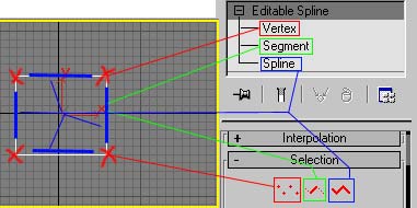
| Step 2: "Get to know your spline". It's very important to understand the parts of the spline in order to model with this technique. There are 3 parts to a spline. The Vertex (marked with the red X). The Segment (highlighted with blue lines) and the Spline itself. | |||
 |
|||
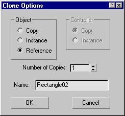
| Step 3: Go back to the main object level and drage a copy of the spline square over to the right. You can simply do this by holding down the shift button on the keyboard while dragging the square. Or just make a copy. You'll get a window that looks like the one to the right. Make sure you check the "Reference" circle. This is going to make our cloned spline a Reference model. Whatever changes you make to the original get transferred over to the Reference. If you make a change to the Reference the change will NOT affect the original. | |||
 |
|||
|
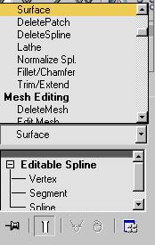
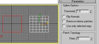
Step 4: Now add a Surface modifier to the "Reference copy". You can find the Surface modifier in the same place you find the "Meshsmooth" modifier. Try this as a tip: when you have the modifiers roll window open try pressing "S". This will let you jump straight to every modifier begining with "S". KEY TO SPLINE CAGE MODELING WITH SURFACE TOOLS. Sit back and let me tell you a little story called Surface Modifier. The Modifier creates a skin between the enclosed area in a Spline Cage that has THREE (3) to FOUR (4) Verticies. A triangle or square surface. If you ever want to put a whole in your skin you need to make sure the area has FIVE or more verticies. Remember, when you add a new vertex to your model you may need to add another to even things out.. We'll get into that in a minute. |
|||
| Step 5: After adding the surface you should get a viewport that looks similiar to this one. Let me explain a few options you'll come accross in the modifiers parameters. When ever you make a surface but the surface isn't visiable try clicking the Flip Normals box. If this dosnt work try increasing the Threshold, default is always 1.0. And if that dosnt work make sure you have the correct amout of verticies in the area where your having the problem. In this case it's simple. In more complex models it can drive a man or woman..or child crazy. Also take note to "Patch Topology". The higher the number the smoother the surface. This also increases rendering time and makes your model very heavy. So a low number is always better. | |||
 |
|||
 |
||||
| Step 6: Now lets try to make things more complicated. No pain no gain. Go back and select the original spline rectangle. Now make a copy of that and size it down to about the size shown here. BE CAREFUL, when you make the copy your last selection will still be active. Make sure you choose "COPY" and not "REFERENCE". | ||||
 |
||||
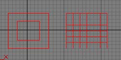
| Step 7: Re-select the original spline rectangle and attach it to the small shape you just created. Look at the reference model in the front viewport.. Now it looks like a patch within a patch. | ||||
 |
|||
| Step 8: Earlier you learned the three parts to a Spline shape. Goto the sub-object level and select "spline" and select the inner square. Now drag it forward in the top viewport and look at the finished result in the perspective viewport. It looks like you have two spline shapes with surfaces? In actuality its just one. We just haven't connected them yet. Click undo a few times and return the center rectangle to the orginal postition. Make sure it's even with the larger Spline. | |||
|
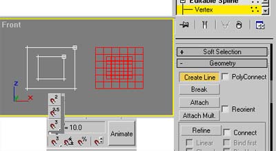
Step 9: Now we are going to create some lines connecting the two shapes. This will give us a "Spline Cage". LINES CAN ONLY BE CONNECTED TO VERTICIES. So we must have the Vertex selected in the sub-object level. Under geometry in the rollout parameters find the button that reads "Create Line" and click it. Also make sure Poly Connect is not checked.. Your selection should look like the one to the far right. Now let me introduce (or re-introduce) you to the Snap Tool. Located at the bottom of the screen next to the animate button. If you LEFT-CLICK and HOLD your mouse button over the button you'll see 3 selections: 2 = for a cage that is flat 3= for a cage that is 3d 2.5= is for anything in-between So for now select the 2 since our cage should be flat. |
 |
 |
|||
|
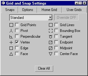
Step 10: After you select the 2d snap tool right-click it and you'll be prompted with this window. This lets you fine tune exactly what you want the mouse pointer to be snapping too. Since we are creating lines we want to check the Vertex option. Just like shown here. Has anyone ever wanted the ability to snap to a Bounding Box?? |
|||
 |
|||
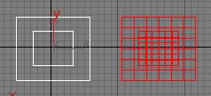
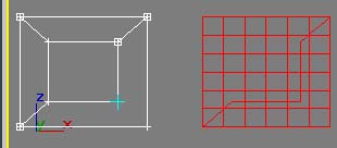
| Step 11: Now go from outer vertex to inner connecting the two squares with new lines. Notice how everytime you run your pointer over a vertex you get a little cross hair. Go ahead and spend some time running the pointer around. It's hours of fun. Enjoy. | |||
 |
|||
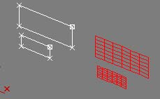
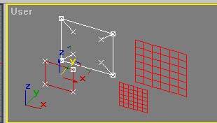
| Step 12: Do as we did few steps back. After creating all of the lines goto the sub-object and select spline. Now select the inner rectangle and pull it out in front of the larger one like shown here. Not impressed?? I did this for a reason. I need to explain the MOST IMPORTANT THING TO REMEMBER ABOUT MODELING WITH SURFACE TOOLS & SPLINE CAGES. | |||
|
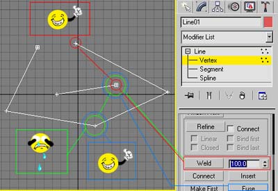
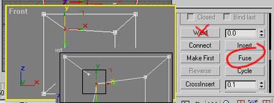
ALWAYS REMEMBER: WELDING: Look at the diagram to the right. Notice in the paramaters window I have a red box around WELD option. I cranked it up to 100. Now follow the red line to the red circles. These two verticies can be welded. Both verticies are open ended so the option is possiable. Now follow the green line. This cannot be done. The vertex on the spline in the middle is open ended but the vertex on the longer spline is enclosed. Thus the welding option is not available. FUSE: Now in the same example locate the FUSE button. Follow the blue line to the two blue circles These (as well with every vertex on the screen) can be fused together. Dont let the word "FUSE" trick you though. This button brings the verticies you have selected on top of each other. This is called COINCEDENTED. Meaning "in the same place". Heres the confusing part. They are not glued, welded, fused, etc. They are just hanging out together. Go ahead and try it. Region select two verticies and click fuse. As you can see they come together fast. LOOKS JUST LIKE ONE VERTEX NOW. TRY LEFT CLICKING THE VERTEX YOU JUST FUSED AND MOVE IT. Notice how you've just split them apart again?? So how do you keep this from happening? ALWAYS ALWAYS ALWAYS ***REGION***SELECT YOUR VERTICIES. This is a very important rule when modeling this way. Because if you seperate two coincedented verticies you'll get a whole in your mesh the size of Kansas. |
||
 |
||
 |
|||
| Step 13: So just to be safe. Region select the verticies on the lines you just created. Like shown here. Do them one by one and fuse them together. This will make sure the verticies that should be together are coincedented. | |||
 |
||
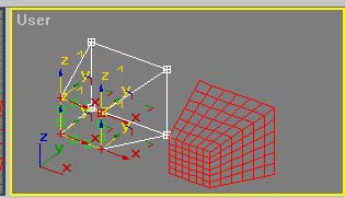
| Step 14: Now lets try this again. Goto the sub-object level and select Vertex and region select ALL the Verticies in the inner rectangle. Now move it forward in the top viewport and inpect your results in the perspective viewport. Now we can proudly say we have a "Spline Cage". | ||
|
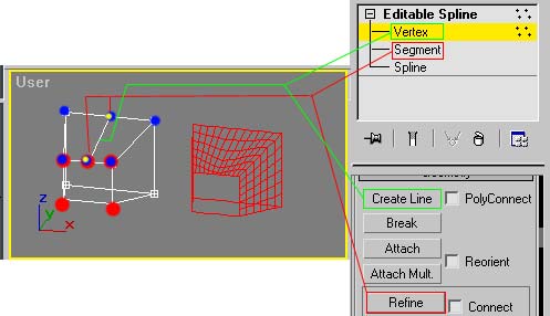
Step15: Now lets make a hole in the model. As we discussed earlier in order to do this we must have FIVE or more verticies in an enclosed spline. This brings us to ANOTHER IMPORTANT TOOL in spline cage modeling. REFINE: In order to use the refine button you must first have the segment selected in the sub-object level of your spline cage. Refine ADDS verticies to any place on a segment. Just run your mouse pointer over and click away. Here we are going to create one in the middle of the top two verticies in the center rectangel. This should make a hole at the very front of our model. It also makes a whole where we dont want one. Because we added that fith vertex we now need to compensate it in the top half. With refine selected add a vertex where the yellow dots are in the diagram. Now select Vertex in the sub-object level and Create Line connecting the two verticies you just created. This will enclose that area and leave the whole where you wanted. |
||
 |
||
|
WORDS OF WISDOM Always remember: Never just click a vertex when you goto move it. Region select it. This way you always make sure you grab any vertex that may be coincedented. Before you move the vertex, make sure you dont have another one that snuck it's way into your Region Select. |
||