Home
| About
| Links
GTO
Main
| GTO
Trans swap | Muncie Rebuild
Jeeps
| Minibike
The
Muncie Rebuild Page
NOTICE!! This Muncie Rebuild is now moved to a new domain: www.SquidsFabShop.com You'll have to go manually and type in the new address since GeeeeeOHCiteeeeez dot calm won't let me link out.
On
the main page, there is a link to this muncie transmission rebuild
guide. It should have no problems with exceeding bandwidth, so it
won't shut you off like this one might. This geocities website
will be taken down in the near future, so update your bookmarks.
This
page is meant to help those considering a
Muncie 4 speed rebuild who have never opened up a Muncie 4 speed
before. I was in this situation and found good information
hard to find on the ‘net. Mainly a lack of good visual
documentation. Well, I think I know why; it's darn hard to
do a rebuild AND take a bunch of good pictures AND put it on a
webpage. Here's my attempt:
I
picked up a 1967 Muncie at a swap meet. I
didn’t really know what to look for so I just checked for
broken parts. The info I found on the internet helped me ID
what I was looking at during my search. It was important to
me to find a late 60’s tranny since it has the larger
countershaft pin, correct spine count (to match my 67 vintage
parts) and speedometer output on the driver side.
I
paid $350 for it and yes, it was too much.
I ran into some old timers who said they remember buying Muncies
at swapmeets for 25 bucks. Sheesh.
To
start:
Get
a manual. I simply have an old Chiltons
manual which lays out the whole process in very basic
steps. It’s got a grainy exploded view so I found a
nice exploded view here: www.autogear.net
Go to the literature section, scroll down
and you can download a great PDF file of Muncie parts with an
exploded view. Study this exploded view. As you look at it, it
may not all make sense, but when you actually tear down the
trans, it will all come together. Manual transmissions really are
very cool mechanisms.
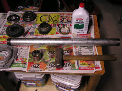
Some
tools I found necessary: A small punch set, a
brass drift set, and a “gorilla” class snap ring plier.
A 2 jaw puller is needed, and of course various hand tools.
Someone
recommended a supplier of muncie parts to
me so I sent some emails and decided to go with them. Bob at www.fourgeartrans.com was
very helpful.
Tear
it down!
I
didn’t follow any particular course of
action, but just went carefully. Here are the main steps:
- Shift
the transmission into two gears:
Twist the shifter shafts CCW (front shaft puts it into 4th,
back shaft puts it into 2nd)
This locks up the mainshaft so
it won’t spin. Take the front bearing retainer off.
- Take off
the “gland” nut, otherwise known as
the input shaft nut. I had to chuck the blasted nut into my bench vise
(not easy with a transmission attached) and turn the whole transmission
by hand. I didn’t have the special wrench until later. Monkey wrench
wouldn't grip it either.
- Shift
the front fork shaft into neutral,
(one click CW). Leave back fork shaft in second gear. This allows easy
side cover removal.
- Remove
side cover.
- Tap out
the reverse gear shaft retaining pin
with a punch. It’s on the side of the boss where the reverse lever
enters the tail housing. Drive it out from the bottom up.
- Unbolt
the tail housing. Pull out the
reverse shifter fork shaft a little bit. Pull the tail housing
off. Ya gotta be fancy to move it around the reverse gear
inside.
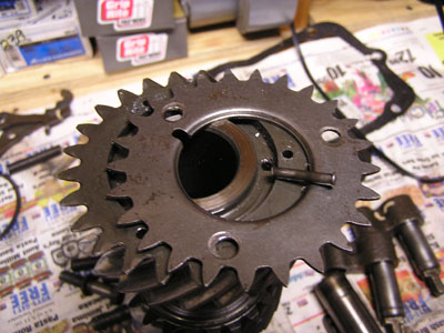
- Take out
the reverse idler gear and
shaft. See figure 1
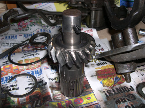
Figure1:
Reverse Idler gear and shaft.
Like the broken teeth?
- Remove
the speedometer gear ring. I used a
puller with homemade extensions to get the jaws to reach the ring. I
also used heat (torch) because that speedo ring was TIGHT.
- Now you
can slide off the big reverse gear.
- Pry off
the midplate from the main case. All
the gear works attached to the mainshaft will come out with it. Roller
bearings will fall out of the input shaft inside the case.
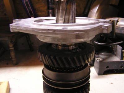
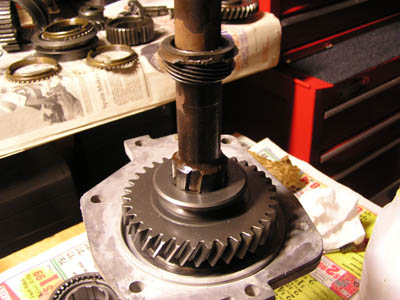
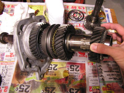
- On the
mainshaft, from the front, remove the
front snapring. You’ll need to flex your gorilla arms to get this
snapring off. Remove the slider/hub toward the front. I had to tap the
hub off; it was a bit tight. Then remove 3rd
gear. See
figure 2.
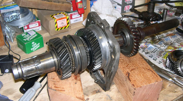
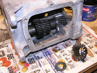
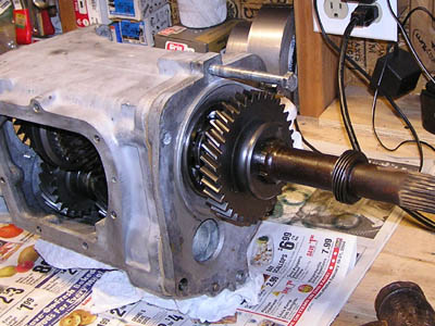
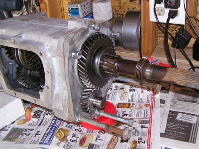
Figure
2. This is the midplate with 1st
and 2nd gear and it’s syncro assembly (hub/slider/and brass
rings). Reverse is hangin' off the back there. 3rd/4th
synchro assembly and 3rd gear are already removed.
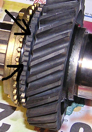
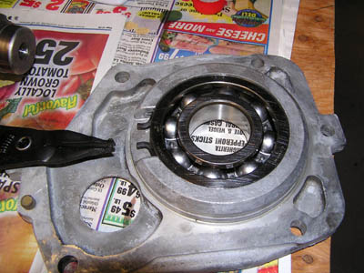
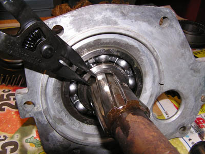
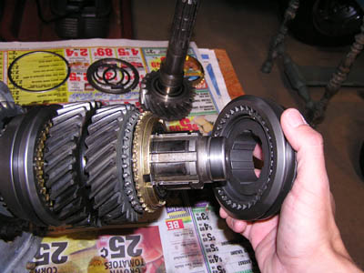
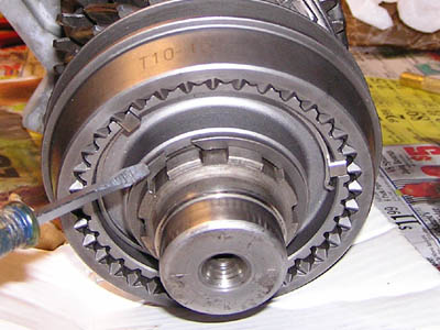
- From the
back, remove the snapring just in
back of the rear bearing. This is a gorilla class snapring
too.
See Figure 3.
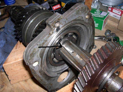
Figure
3. Arrow shows back snap ring.
- I then
brought the
mainshaft-midplate-bearing-1st-2nd
gear assembly
to a machine shop to press everything off from the shaft. (bearing, 1st
gear bushing, and finally the synchronizer hub) One source on the ‘net
said he just takes the assembly and smacks the tail of the mainshaft
onto an aluminum plate on the floor a bunch of times to force off the
parts. Seems violent, but it works. Since I had it done at a shop,
everything came off at once.
- 2nd
gear can now be removed. You
should have a bare mainshaft now.
- For the
case, first, remove the reverse
idler front gear and thrust washer. It’s hangin’ loose in
there.
Refer to your exploded view! You can now tap the input shaft into the
case and take it out. Remove the bearing by tapping it out to the front
using a drift from the inside. It shouldn’t be in there too tight.
- Now to
remove the cluster gear (counter
gear): Use a big brass drift and drive out the countergear pin from the
front to back. After a few good hits it’ll slide right out. Lift the
counter gear out. Lots and lots of needle bearing will pour outa there!
Take out the bearings and spacers and thrust washers too.
- There
may be a sheet metal “gear” riveted
onto the front of the gear. It’s some sort of anti-rattle mechanism,
but it’s been known to come apart and destroy the main case. It’s not
needed anyway, so I drilled out the rivets and removed it. Figure 4.
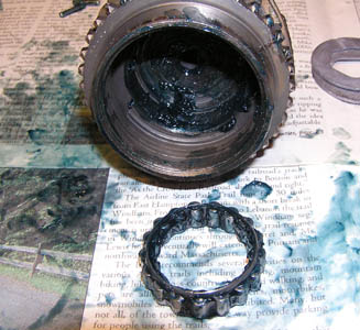
Figure
4. Rattle gear taken off. Notice
rivet on top after being punched out. Spring underneath is
removed too.
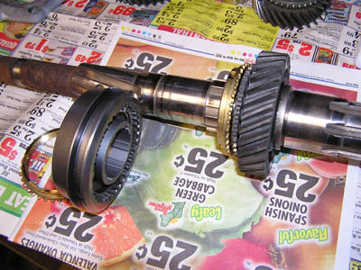
Now the
main case should be bare.
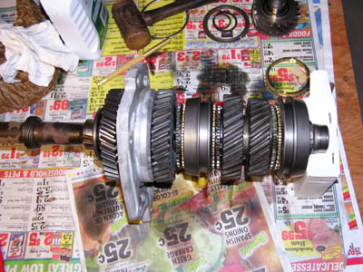
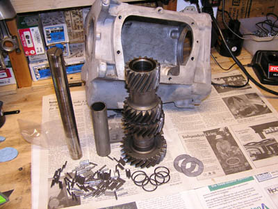
Take
a look at all the itty bitty parts. Time to
wash ‘em and the case too. Time to determine what you need
to do a good rebuild. My gears were in good shape, although the
engagement teeth on third gear were a bit rounded off. The
engagement teeth are the little “nubs” on the sides
where the cone shape is. See Figure 5. The sliders grab these
teeth when the gear is engaged. If they’re rounded off too
much, the gear will push the slider off and back into neutral.
Reverse gear has no synchro, hence no little engagement teeth.
Figure
5. Black arrows show the engagement
teeth. These are in good shape. Brass synchro (otherwise known as
the blocking ring) is installed over the cone portion of the
gear.
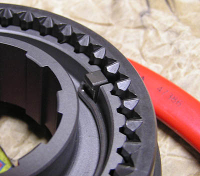
I didn’t
want new
gears so I talked to the
Fourgeartrans guy and he recommended Torque loc sliders. These
help keep your gears engaged especially if your gear’s
engagement teeth are a bit worn. Normal sliders are straight
splined. Note the Torq-loc splines. On the left is the destroyed
original, and on the right is the Torq-Loc. See figure 6.

Figure
6. The original
was in pretty bad shape (left). Torq-Loc slider on the right.
I
sandblasted all the case parts since they were
really stained and dirty. I tried chemicals, but the finish was
still stained and ugly. I used fine Olivine blasting sand. Lot's
of work but it looks good.
I
repaired a stripped hole in the tailhousing with
helicoil, and also fixed a hole in the tailhousing from a long
bolt used on the shifter mounting plate. I used JB Weld epoxy
to seal it up. This is good stuff!
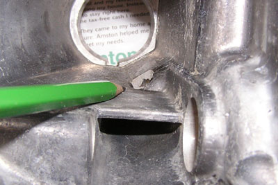
Figure
7. Blasted case on the left, pencil
showing hole in tailhousing on right. Nothing a little judicious
use of JB Weld won't take care of.
So get
your rebuild
kit and let’s get started
on the….
Rebuild!
- Assemble
your synchronizers. The
synchro hubs have a flat side and an extended side. The extended side
will face front for both 3rd/4th
assembly, and 1st/2nd
assembly. The slider (i.e. sleeve, i.e. clutch) for the 3rd/4th
set is slipped over the hub so the tapered side faces front. The 1st/2nd
slider in slipped over it’s hub so the the taper faces the rear. Figure
8a and 8b.
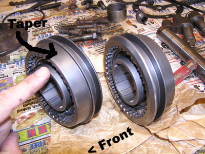
Figure
8a. Synchronizer assemblies. 3rd/4th
is to the left, 1st/2nd
is to the right. Hubs are already inside the sliders. Finger
points to hub extension. The analogy used frequently is the
assemblies stacked together look like “a hamburger bun”
as you look at it.
Figure
8b. This detail shows the spring holding the key in place. The
spring holds all three keys in. It is the same on the other side.
Note the orientation of the keys.
- Put
some oil on the main shaft and
slide on second gear with a synchro. Cone side toward rear. See figure
9a.
- Slide
on the synchronizer assembly
(the one to the right in figure 8) with the hub extension toward the
front. I used a brass drift and tapped it on. Make sure the brass
blocking ring is aligned so the 3 wide gaps fit over the keys in the
synchro assembly. Also, careful you don't knock the synchro assembly
apart. See figure 9b.
Figure
9a and 9b. Correct orientation of synchro assembly to be
installed.
- Now
you can place the 1st gear
bushing on. This will need to be pressed. I used a 2 foot length of
1-5/8 I.D. steel pipe. See figure 10a and 10b.
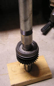
Figure
10a. In the foreground we find on the left: 1st gear sleeve, to
the right one beating shalilly, and in the middle one steel pipe.
Figure 10b is the pipe pressing the sleeve down to the hub. Make
sure you tap it down all the way.
- With
the shaft tail sticking up in
the air, install a brass blocking ring into the synchronizer assembly,
being careful to align the notches with the keys, then lube up the I.D.
of first gear and slip it onto the bushing. See figure 11.
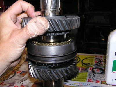
Figure
11. Blocking ring is in the synchro assembly (align the 3 notches
in the blocking ring with the keys in the synchro), and first
gear is about to settle in.
- Time
to press the rear bearing into
the midplate (rear bearing retainer). Put in the bearing snapring
first, expand the snapring and press the bearing into place. Press it
in until the snapring snaps into place. Tapping may be necessary. See
figure 12.
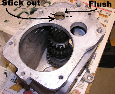
Figure
12. Snapring locates bearing. Make sure the bearing is facing the
right way or it'll be sticking out of the midplate.
- Place
the midplate onto the
mainshaft and press the bearing down until it hits the first gear
bushing. Again, you may need the help of a hammer and pipe. See figure
13.
Figure
13. The midplate isn't pressed on yet here, but you can see the
locating lip of the midplate is facing down. This will register
it with the maincase when the time comes....
- Install
a snapring in the groove
directly behind the rear bearing. The rebuild kit should have several
thicknesses. Pick one so it's as small a gap as possible when
installed. Place it so the ends are behind splines. I don't know why,
but they want you to. See figure 14.
Figure
14. Still not fun trying to wrestle this sucker on even with the
right tool.
- Install
the reverse gear with the
flange facing toward the end of the shaft. Install the speedometer
ring. I used the old input shaft nut as a washer in between the pipe
and speedo ring so I wouldn't bugger the speedo ring. See figure 15.
- Test
fit the tailhousing onto the
midplate and look to verify the speedo ring is lined up in the middle
of the speedo cable hole.
Figure
15. Notice the old input shaft nut as a washer for banging on the
speedo ring.
- Time
to install the 3rd and 4th
gears onto the front of the mainshaft. First, oil up the I.D. of 3rd
gear and slip it onto the mainshaft with the cone facing forward. See
figure 16a.
- Install
the synchro assembly with
the hub extension facing forward also. This may need to be tapped on
with some slight persuasion too. See figure 16b.
Figure
16a. 3rd gear is being slipped on. Cone toward the front. Figure
16b. Now the synchro assembly is being placed on. Make sure to
tap it on all the way.
- Now
the front snapring can be
placed on. Orient the snapring so the ends are behind a spline. See
figure 17a.
Figure
17a. Here is the front snapring installed. Notice that it says
T-10 on the slider. T-10s and Muncies share many common parts.
Figure 17b. Your assembly should look like this!
- Time
to get to the maincase and
cluster gear. Get your jar of grease ready. Study your exploded view
for the sequence of parts.
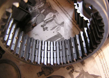
- Pack
some grease into the cluster
gear center and place the long spacer inside. Place a single thin
washer in, then smear grease around the inside. Start packing in the
roller bearings. Pack as many as will fit. Place another thin washer on
top and press the works inside. Smear more grease around the inside,
then pack more roller bearings (as many as will fit). Place yet another
thin washer on top and press it flush with the end of the counter gear.
- Go
to the other side of the counter
gear and put a thin washer in there, smear some grease, pack in roller
bearings, another thin washer, more bearings, then the last thin
washer. Figure 18b shows the roller bearings inside.
Figure
18a. Case and countergear. Figure 18b. You can see from the edge
on down: thin washer, roller bearings, thin washer, roller
bearings, thin washer, and yep, the big long spacer is in there.
Same for the other side.
- Apply
grease to the back side of a
thrust washer. These have a tab which fits inside the notch in the
case. Squash them into place on each end of the case. See figure 19a
and 19b.
- There
seems to be many methods to
do this next part. I found it to be very easy for some reason. Many
have said it takes many tries, but it was so easy, I was surprised.
Here's what I did:
- Place
the main case so the front
end is on the bench top.
- Manuever
the counter gear into
position with care. Ensure that the thrust washers stay in place. Use a
screwdriver or your fingers to put the thrust washers into postion.
- Take
the countershaft pin, flat end
first and push it down into the countershaft hole. Wiggle the
countergear to help it along. The pin should go all the way except for
the last half inch or so.
- While
holding the countergear with
one hand, tip the case on its' side and use a finger to align the front
thrust washer and guide the pin to the front hole in the case. Once it
finds the hole, it will need to be pressed the rest of the way. BEFORE
YOU DO: Make sure the pin is aligned correctly. On the rear part of the
case, the raised part of the pin is up and as you look at it from the
rear. It should aligned to the 8:00 o'clock and 2:00 o'clock positions.
Figure 20b.
- Tap
the pin in until the notched
part of the pin is flush with the case.
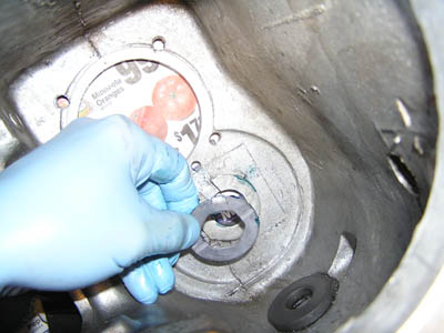
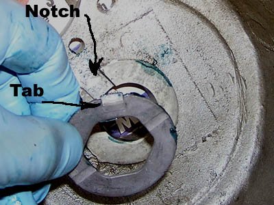
Figure
19a and 19 b. Thrust washer being installed on front of case.
Figure
20. Note the orientation of the pin notch.
- Now
place the case on its' side and
install the front reverse idler gear thrust washer. It also has a tab
which mates with a notch in the case.
- Install
the front reverse idler
gear. It will be loose for now. Figure 20.
Figure
20. Front reverse idler thrust washer and gear (not installed yet
in photo). They'll be loose until the rest of the guts are
insalled.
- Load
the input shaft bearing cage
with their roller bearings. They are installed from the outside. Grease
will hold them in.
- Load
up the input shaft roller
bearing area with grease and slip the cage and roller bearings inside.
see Figure 21.
Figure
21. The input shaft is ready to have the bearing cage and roller
bearings place inside.
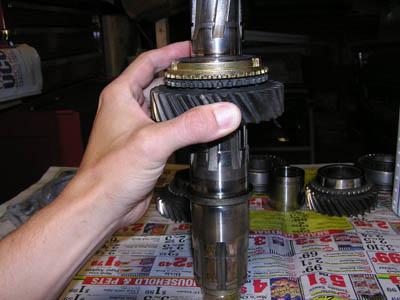
- Place
the last blocking ring into
the 3rd/4th synchro. Make sure the notches line up with the keys. Place
the input shaft assembly onto the mainshaft. The insider roller
bearings will slip over the mainshaft tip. See figure 22.
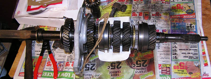
Figure
22. This is the whole shebang. The 3rd 4th synchro is slipped
over to engage the mainshaft (4th gear position) to help hold the
input shaft on for the next step.
- Slip
the front midplate gasket into
position. I used a thin bead of silicone to keep it in place.
- Apply
a bead of slicone to the back
of the maincase.
- Lift
the gear assembly into
position at the rear of the main case. Put your hand inside and guide
the gears into the case. Keep going until the midplate is against the
main case. Align the dowel pin and then tap the midplate until it is
seated. Since I was taking my time and I wouldn't get to the tail
housing until later, I used some bolts to snug it all down to "seat"
the beads of silicone. I let it sit overnight to cure. See Figure 23.
- Slip
the reverse idler pin into a
liberally oiled reverse idler gear. Slip it into the case and manueuver
the front idler gear so the splines engage. Be careful to make sure the
tabbed thrust washer stays in place inside the main case. Figure 23b.
Figure
23a. The midplate
has been tapped on. Figure 23b. Bolt the whole thing on to seat
the silicone. Also note the reverse idler has been installed.
It'll still be a bit loose until the rear of the pin is seated in
the tail housing.
- Time
to install the front bearing.
Place the snap ring onto the bearing. Place it over the input shaft and
press or tap it down until it seats in the main case.
- Lock
the transmission into two
gears. This will keep the mainshaft/input shaft from turning.
- Install
the left hand input shaft
nut. Tighten it up. I bought the correct wrench, even though it was a
bit pricey. I don't want to monkey with a monkey wrench for this one.
Use loctite, and/or stake the nut to the mainshaft.
- Install
the gasket on the bearing
retainer. I used slicone on the gasket. Align the retainer so the oil
drain path is correct then bolt it on. Use sealer on the bolts!
- Tail
housing time: Press or hammer
out the yoke bushing. I used a 1-1/4 inch socket which fit perfectly.
Install the new bushing. I used a piece of hard wood to start it, then
as it went below the outer seal lip, I used big washers to hammer on.
Drive it in until it is flush.
- Install
the rear seal.
- Install
the seal for the reverse
lever shaft. A 3/4 socket is perfectly sized to tap it in.
- Install
the spring and ball bearing
into the hole for the reverse lever.
- Install
the reverse lever as far as
it will go. The lever must be pressed in so the ball is bearing against
the detents on the shift arm:
- This
gets tricky: How do you press
the spring and ball down and push the reverse lever in all the way? I
used a piece of shim from a feeler guage set to use it like a shoe
horn. It worked very nicely, but the shim was slightly mangled. (When
is the next time I'll need an 0.008" feeler guage anyway?) See figure
24.
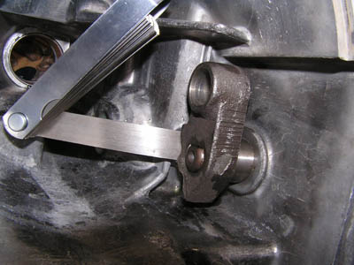
Figure
24. The shim is
being used to shoe horn the lever past the spring loaded ball
bearing. Shown here, the reverse lever shaft still needs to be
pushed toward the outside of the case about 3/8 of an inch.
- Rotate
the reverse shifter arm
forward so the ball bearing is pressing on the bottom detent. This is
the engaged position for reverse gear.
- Now
pull the reverse lever shaft
out of the case as far as possible. Be very careful not to let the ball
bearing spring out past the lever. The lever needs to be in this
position to allow the tail housing to slip onto the main case and
reverse gear while you install the tail housing.
- Place
the reverse shifter fork
(forklet?) into the reverse shifter arm. Align it so its' slot is
vertical
- Slip
the gasket onto the midplate.
- Move
the reverse gear out to the
rear of the splines it rides on (reverse gear disengaged).
- Manueuver
the tail housing over the
tailshaft and line up the fork over the reverse gear flange. Once the
fork is on the flange, align the reverse idler shaft into the tail
housing and then push the tail housing on all the way. Tap the
tailhousing the last bit if needed, but don't force it.
- Push
the reverse shifter shaft into
the case now so you can see clear through the hole the tapered
retaining pin goes into.
- Make
sure the 1/2 and 3/4 synchros
are in nuetral, and then rotate the input shaft and see if it is indeed
in reverse.
- With
pliers, rotate the reverse
shifter shaft CW. This disengages reverse and you should now be in true
nuetral.
- Install
the tapered pin to lock the
reverse shifter shaft into position.
Figure
25. Tailhousing installed.
- Time
to assemble the shifter cover
plate. Install the seals in the shifter plate. A 3/4 socket works
nicely.
- Install
the detent levers.
- Install
the spring.
- Install
the shifter shafts with
forks. Pull the detent levers up to push the forks in all the way.
Leave the 1st/2nd lever rotated toward the left, or 2nd gear position.
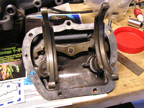
Figure
26. Here is a detail of the shifter forks installed in the
shifter plate.
- Place
the shifter cover gasket in
position and manuever the cover on. Install all the bolts and torque
them on.
- Install
the speedo driven gear
housing.
- You
are done, but, DON'T FORGET TO
FILL IT WITH OIL BEFORE YOU FIRE IT UP!
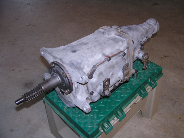
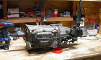
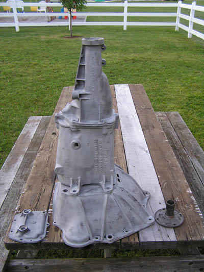
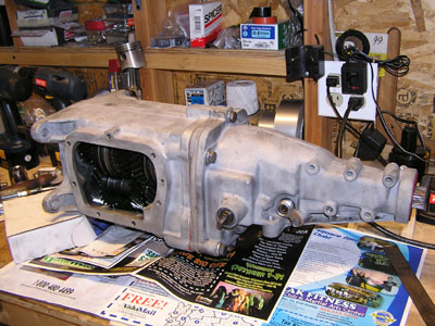
The
finished product. Kinda ugly isn't it? I am going to do a final
scrubdown and maybe clear coat it.
This was
a very
rewarding project and it really isn't that hard.
This is
my first cut
at putting down the whole procedure so if you see anything amiss,
I'd appreciate any feedback. See my About page to get my email
address.
Views
since November 2004:

Home
| About
| Links
GTO
Main
| GTO
Trans swap | Muncie Rebuild
Jeeps
| Minibike
Dave
Miles
October 10, 2004