The present day requirement for ever-increasing reliability in the field of rotor dynamics is now more important than ever before and continues to grow constantly. Advances are continuously being made in this area, due largely to the consistent demand from the power generation, transportation industries and high-tech application like space technology. Because of progress made in engineering and materials science, rotating machinery is becoming faster and lighter, as well as being required to run for longer periods of time. All of these factors mean innovative design of rotating parts for minimizing the overall maintenance cost and time. Designing such a system requires adequate knowledge in associated fields of science like vibration analysis, tribological mechanisms, material science, control techniques and more. Command over these vast areas of science is hardly possible for an individual which forced the researchers to ignore some.
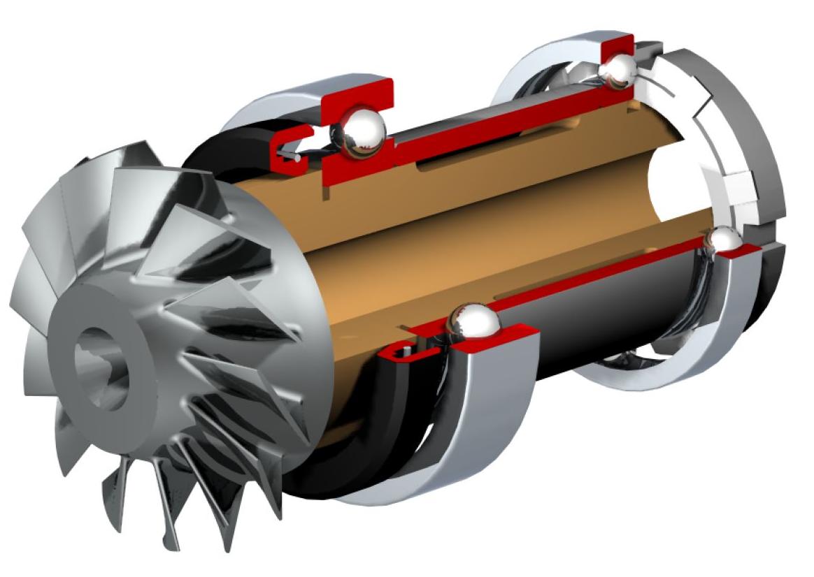
Figure 1.1 Assembly of a turbine
Designing rotary machinery refers to the design of different
associated components, like rotor, bearings, dampers, stiffeners, support
etc. Figure 1.1 shows a simple turbine assembly with two ball bearings. Ball
bearings are the most common and important member in replacing sliding by
rolling friction, thus to reduce the friction between a fixed and moving
surface. A common ball bearing consists of a number of rolling elements and
two rings, the inner and outer ring (see Figure 1.2). Both rings have
grooves or raceways to guide the rolling elements. The rolling elements are
separated from each other by a cage. To reduce the friction and wear in the
rolling contacts, bearings are lubricated with oil. The part of the
surrounding structure that is connected to the bearing is usually referred
to as the housing. The bearings and the housing have to provide sufficient
static support for the shaft.
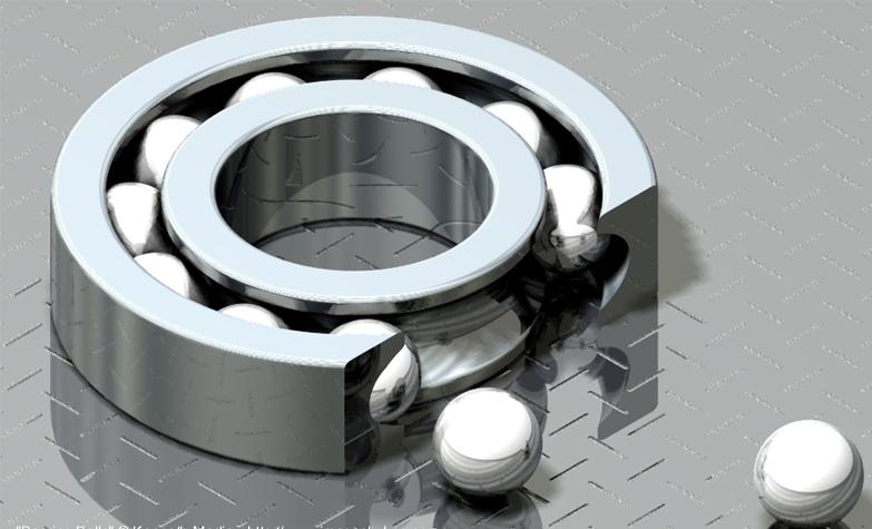
Figure 1.2 Example of a deep groove ball bearing
The technology to manufacture rolling element bearings with sufficiently high load carrying capacities was developed about 100 years ago, several thousand years after its invention. Since then, ball bearings are used in many kinds of machines and devices with rotating parts under desirable functions such as
- Low starting and good operating friction.
- The ability to support combined radial and thrust loads.
- Less sensitivity to interruptions in lubrication
- No self-excited instabilities.
- Good low-temperature stating.
Today, about 4 billion bearing units are manufactured worldwide each year, which corresponds to an average production rate of more than 125 rolling element bearings per second.
In the past, the design of rolling element bearings with increased service lifetime and theoretical prediction of bearing fatigue was main objective of research and development. Now a days, standardized procedures to predict the bearing lifetime can be found in bearing catalogues or handbooks. Due to increasing demands concerning a quiet and vibration-free operation of rotating machinery and thus, the growing importance of dynamical problems in mechanical engineering, an adequate theoretical description of the dynamic properties of bearings and joints within mechanical structures is the centre of today’s interest. An important feature of ball bearings, with respect to the dynamic behaviour of the application, is their inevitable presence in the transmission path of vibrations from shaft to the housings. The transfer of vibrations through ball bearings largely depends on the stiffness and damping in the lubricated rolling contacts between the balls and the guiding rings. In general, the stiffness and damping of these contacts depends on the load distribution and deformations in the whole application. This implies that the bearing has to be considered as an integral part of the application.
The stiffness estimation of dry contact rolling element is well understood up to some extent, only little information is provided concerning the damping of dry contact as well as stiffness and damping of a lubricated rolling element bearing. In particular, there is no standardized procedure available to estimate the stiffness and damping of a lubricated rolling element bearing. This may be due to the fact that the theoretical description of the complex physical process within a lubricated rolling contact is a highly sophisticated problem. Currently an attempt has been made to solve this problem theoretically.
Due to the increasing capacity of modern computers and the development of advance numerical tools the investigations are supported more and more by means of numerical simulations. A solely experimental approach is generally avoided because experiments are costly, time consuming and less universal than computer models. Moreover, in the case of ball bearings, an experimental approach often leads to a complex analysis because the individual vibration source cannot be isolated and measurement sensor is always positioned outside the bearing. An additional complicating aspect in ball bearings is the rotation of the different components.