Laptop OC project (Finnish version)
(links to more pictures at the end of the page)
The beginning
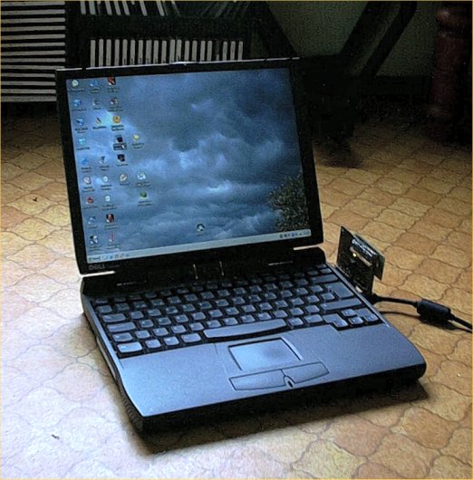
Dell Latitude CPiA:
P3 450Mhz
128Mt Kingston ValueRam PC133 Cas3
12Gt Fujitsu
13.3" (as i recall) LCD
floppydrive as Modular Bay-module
Paid 400 of it, used of course (it came with C/Port docking station, which i sold for 40 , so 360 ). No battery or CD-drive.And Latitude CPiA's bios doesn't support P3's microcode, but everything works. So it was a bit 'tweaked' allready :).
After little searching i found these parts:
mediocre battery, about hour working time.
processor P3 500Mhz.
memorystick Mitsubishi 256 Mt PC100 Cas2.
DVD-drive Toshiba SD-C2302 Modular Bay.
Upgrade cost ~110 . And Jurpo came to my possession some time ago for ~30 . So final prise is around 470 . Rest of the parts used were found from various boxes full of broken or just abandoned stuff :).
Overclocking
As i was searching for a laptop, i was offered two used machines. Other was a Toshiba Tecra, and this Dell. Toshiba was equipt better, but with slower cpu. The factor that turned me to this Dell is the possibility to use 500+ Mhz P3's :). Of course, when i got this machine, i opened it up. And i even got it back together. And first thoughts of overclocking were finding their way in my mind :). The final sparkle came from a thread in finnish BBS (MuroBBS) where one guru was working his magic on a IBM Laptop.
Settings for overclocking are usually non-existent when it comes to laptop. Mostly the bios is also very basic, and the settings are for security and power options. So no Cas-latency or FSB there. And as the CPiA's clockgen (IMI SG556) isn't programmable, no Windows software could be used to make adjustments. So it's hardware all the way, baby ;).
Cooling
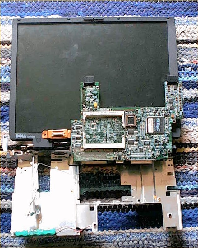
Before i started modding the motherboard, i checked if there's a possibility to enhance cooling. Pentium 3 was showing temps of 70+ celsius with original cooling solution. This is understandable, if you look the size of the cooling element , esspecially the heatsink :) (on the left side of the aluminum plate, the rectangular thing). And the machine supports officially only up to 400Mhz P2.
The fan is controlled by Dell's bios by following manner:
68 degrees celsius kicks the fan on, slow mode
if fan is on, and temp lowers below 60 degrees celsius, fan stops.
i can't remeber seeing the fan at fast mode, seems it must be around 80 :).
There were few things i could to improve cooling:
original heatpad between cpu and heatsink didn't get my approval. So it left and some better thermal compound entered. Results: the max-temps remained, but idle-temps got little lower. And cpu cools down much faster, meaning that when cpu load goes down, fan stops very soon. Before getting the fan to stop took minutes, and even very low load (~25%) was enough to keep cpu at 60+.
the keyboard has a metal plate as a back. And almost in touch with heatsink. I added few pieces of aluminum plate in between, spiced with thermal compound. And one piece for graphics chip (MagicMedia 256AV). Results: when the machine is cold (not used for few hours) it tooks noticeable longer before fan kicks in. Same maximum temps. Of course when keyboard heats up, temps go up also. But should keep my fingers warm during winter :).
Modification
When searching the clockgen for first time, i literally had to take the whole machine to pieces. Only the motherboardtray and display were attached, rest of the parts were scattered across the room :). More close examination showed that removing a ~4x2cm piece from the motherboard tray would reveal clockgen when opening the slot for accessing memoryslots. Neat and easy, no need to start massive hacking of the plastic case.
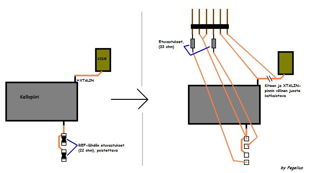
Clockgen did prove a bit problematic, cause no datasheets could be found at first. Luckily the thread in MuroBBS gave an idea to compare the chips measuring results to Pericom:n PI6C102's datasheet and pin-arrangement. Suprisingly they seemed to be the same. And when i actually only needed to replace XTALIN and two REF-signals, it was pretty easy afterall. Luckily the I/O-stuff is controlled by SMSC FDC37N958FR and has it's own crystal, so everything should work.
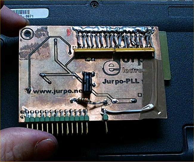
With the final modification i ended with following solution: i attached this (6 'spikes') to the motherboard, near clockgen. Motherboards original freqs and their 'target's are there, so i can feed some other signals, or revert to original signals by using jumpers. I removed SMD-resistors from motherboard and cut the trace from XTALIN to crystal. So it's really easy to revert to default speed if necessary.
Needed external freqs come from module called JurpoPLL v.2 from Jurpo Electronics . It's like basic TurboPLL-module, but it's specifically made for this kind of application, and has a variable frequency feed instead the crystal changin method used with TurboPLL. The variable freq is adjustabe with very fine increments.
The installation went quite well, because i can still close the memoryslot cover and it doesn't look too bad, actually ;).
Results
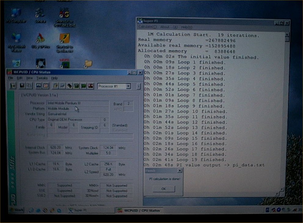
Completely stable speed is around ~605Mhz (121 FSB). Cooling isn't good enough for using higher speeds for longer periods, even though 620 works ~15 minutes stable before it becomes unstable. Highest i can get it to post is @135FSB, but Windows loads only max ~128Mhz FSB. Max temps are around 75 degrees celsius (with fan on slow mode).
Of course extra speed isn't the only benefit this module brings; when talking about laptop, things like battery lasting time is in your mind. So if i need some extra working time, or need a quiet and cool machine, i can do following:
bios-setting CPU Speed -> Compatible reduces speed to 125 Mhz:iin (25Mhz FSB :). And Jurpo offers extra flexibility for that setting ;).
And of course using only Jurpo. ~70Mhz FSB (350Mhz CPU) should do very well when doing text edit and some work. The beauty of it is that there's so many FSB's :).
Also, a kind of information protection; if someone manages to steal this machine without Jurpo installed, i think that person is going to have a hard time getting it on ;) (unless that person has read this page...).
In the future, voltagemods, trying to improve cooling... when time and inspiration is on my side.
Updaattimus
Ok, changed to Vcore of the cpu and tested how things change. This P3 500Mhz MMC-2 processormodule has Semtech SC1406A controlling the Vcore. Closer examination showed that easiest way to change the voltage is to alter VID-pin states (gnd=0, nc=1). Hearing that low means good with Mobile, i started with quite large jump, from default 1.56V to 1.36V. This required the removal of one puny 0-ohm SMD-resistor :).
I also made some adjustments to cooling, now BX-chip's heatspreader is connected to heatsink.
Results:
@ default speed with full load temps went down ~10 degrees celsius. At 68 degrees fan kicks in and temps go down to stable 63. If fan is on high mode, temps fall 1-2 degrees.
even when overclocked there's ~8 degrees improvement. It posts @ ~690, but it seems that it's the mem that's holding me back even @127 FSB. 124 FSB (620Mhz) seems stable even during longer periods.
battery lasts little longer. Especially if i downclock. Making notes at school and ~3 h is very common (depends how much the teachers want make us suffer :). I also did the freezer trick (3 days in freezer, 1-2 days unused in roomtemp and then long recharge) and got ~10% more time.
Pictures
Ah the joy of bringing it to pieces
27.8.2003
(19.08 English translation and update)
(4.8.2004 updated formatting)
Pekka Piippo aka Pegelius