Super AFC install How-To
Courtesy of Jeremy S.
Midwest NRG
First and for most it is very important to visually double check all the information giving here for your car. Please do not rely on second hand information when working on your personal vehicle.
As stated Apexi does not list the Neon as being a vehicle that can be hooked up to the unit. Upon extensive research by others, we made all the proper conversions and pin out connections. Thank you to all the people on Neons.org as well as other DSM boards for your input. And thanks to Modern Performance where I bought my AFC from.
I have written a UPDATE for adapting to the 1995 style of wiring harness. -JS
Thanks to Adam W. for the 2ND GEN WIRING HOW-TO. -JS
We have not done any dyno tuning (recommended) with the Super AFC yet. We anticipate doing this soon and results will be posted here when available.
UPDATE: I have seen gains as high as 8whp and 5ft lbs after dyno tuning.-JS
The vehicle used was a 1998 Dodge Neon R/T. It has many of the popular bolt ons currently including: CAI, UDP, Race Version PCM, Port and Polished intake manifold, P&P throttle body, aftermarket exhaust including header and axle back muffler.
Here we go......
I apologize for the lack of photo's in this how-to but there wasn't much too look at.
As always, be sure to unhook the negative connection at your battery. This is especially important due to the fact that you will be removing the PCM and disconnecting it.
Now you will want to remove the 2 10mm screws that secure the PCM to the fender skin, and the 10mm nut toward the top left of the PCM. Also, remove the washer fluid tube by simply pulling it out. The computer is now able to be lifted out of the mounting location. At this time unplug the 2 large connectors at the top.
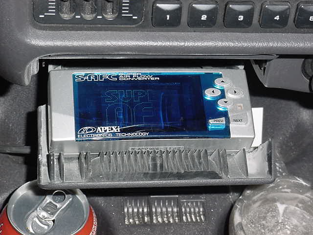
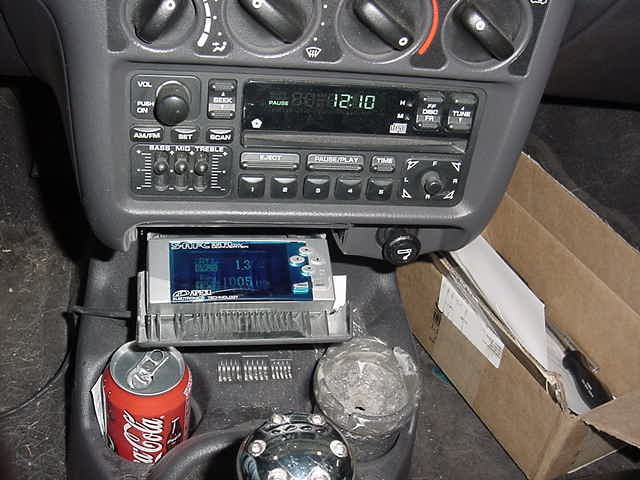
The unit comes with the controller unit with a pigtail DIN cable coming from it. There is a connector midway that terminates in a bunch of wires. You can mount the control unit anywhere you please. Eric opted to modify his ashtray as show below. It looks great and is very stealthy.
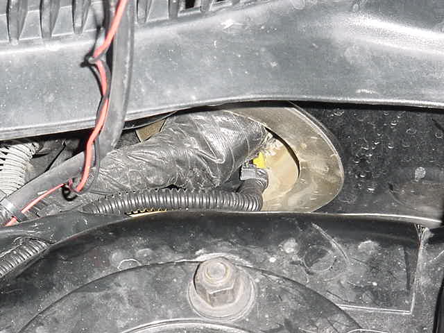
There is a large, rubber grommet that runs through the firewall on the drives side. Run the wiring cable through here with enough slack for the wiring to reach the PCM plugs.
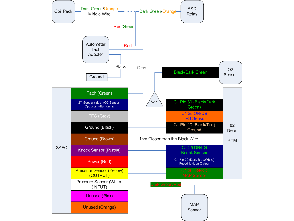
Now you will want to locate and identify the proper wires that need to be spliced and cut into. The wiring color codes and pin outs for the neon are as follows:
Power wire: pin 20: Dark Blue/White
Tach signal (RPM): pin 73: Grey/Light Blue
Throttle sensor (TPS): pin 35: Orange/Dark Blue
Ground wire: pin 10: Black/Tan
Press. sensor (MAP): pin 36: Dark Green/Red
O2 sensor: get at upstream O2 black wire or pin 30
The wiring information for the Apex unit is as follows:
Power: Red
Tach (RPM): Green
Ground: Brown
Throttle: grey
Ground: Black
O2: Blue
MAP input: White
MAP output: Yellow
(*note, it is very important to follow Apexi's directions exactly when it comes to making the connections to the wiring. We used solder and heat shrink tape to make all of ours. Be sure to double check the connections because the last thing you want to stop working is your MAP or TPS or even Tach signal wiring.)
Make the proper connections wire to wire. We stripped back about 1cm of insulation and wrapped approx. 1" of wire around that and secured with solder. Also be sure to note that the brown and black wires from the Apex unit are very picky when it comes to connections. The Brown wire must be spliced in 1cm closer to the PCM than the Black wire. This is important since the unit basically works off of varying voltages. Also, you must cut the MAp sensor wire to make that connection. With the stock wire cut, connect the white wire to the motor side and the yellow wire to the computer side.
Now make the connection between the wiring harness and the Apex controller. Plug in and secure the PCM, then LASTLY reconnect the negative battery terminal.
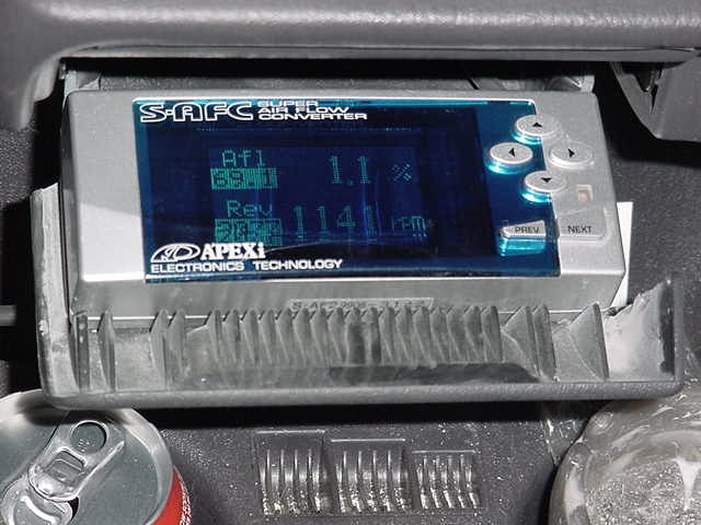
You will want to turn the car on to the accessory position but do not start it quite yet. Program in the following settings prior to starting up for the first time:
These are the three "initial settings":
1 - Pressure sensor is type 6 (6 in 6 out). Some people have been using a 5 in and 5 out with no problems. We have been running that way and it has been fine.
2 - throttle arrow should be pointing up.
3 - cylinders should be set to 4 (duh)
Before you start it up turn the key all the way off and back on, now go ahead and fire it up. If programmed to the settings above your car should idle fine and smooth with no notice in change. Be sure to check for any Check Engine Lights (CEL). Diagnose as necessary.
To finish up the project, rewrap the wires around the PCM connectors securely, remount the PCM, route and secure the wiring for the Apex (zip ties) and secure the wiring coming into the car from the firewall.
That should be about it. If you have any questions, comments, or feedback on this how to or others, Please sign the Guest Book that is linked at the bottom of this page.
Where to buy one? Check out Modern Performance for one.

