Identifying the parts
Lift base and cover unit from the carton and remove dust cover (if present). Carefully lift out platter, motor housing, power supply, etc. Remove the large polystyrene housing to enable removal of the aluminium chassis from the bottom of the carton. For Gyro SE, remove the spider from the underside of the polystyrene housing.
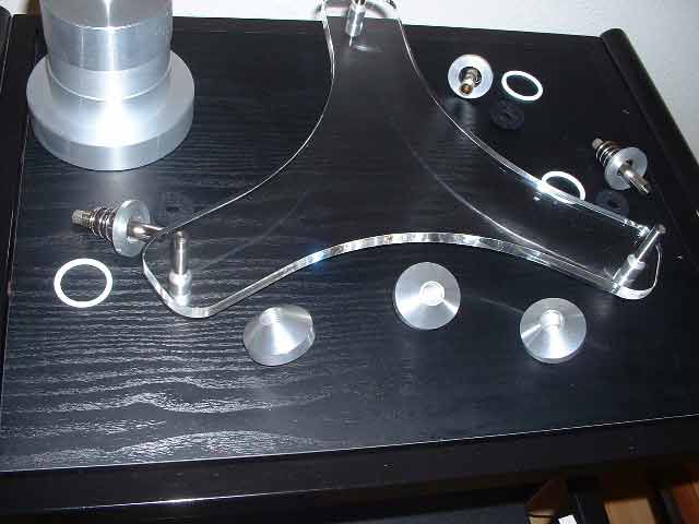
Then check the contents of the package:
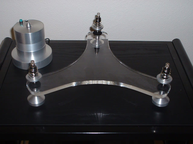
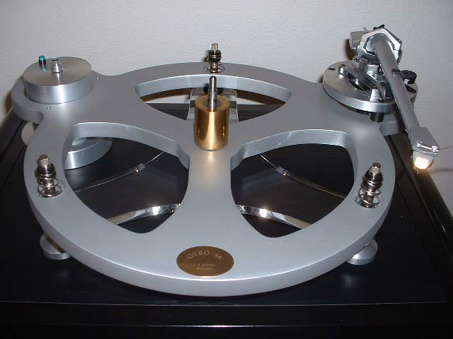
- one acrylic base (GyroDec: plinth; Gyro SE: spider)
- two sets of hinges (GyroDec only)
- one dustcover (GyroDec only)
- three coned feet
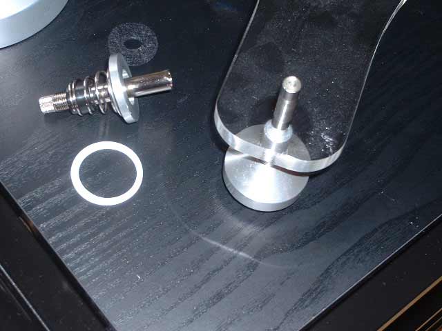
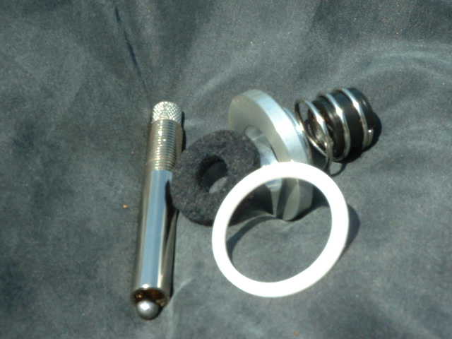
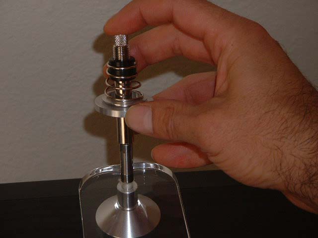
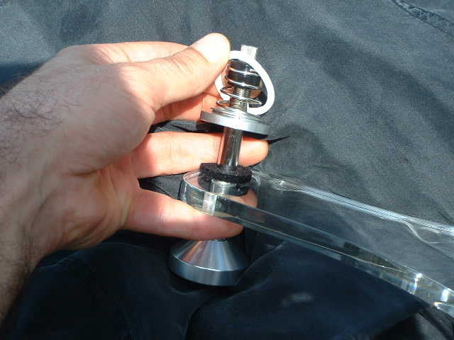
- three spring support studs
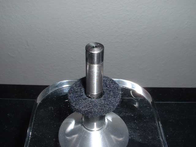
- three upper spring towers with internal thrust ball
- three spring assemblies
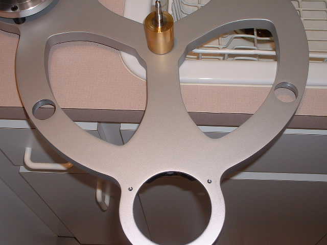
- one cast aluminiun (sub)chassis or 'Mickey'
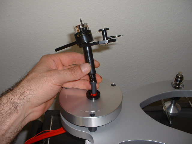
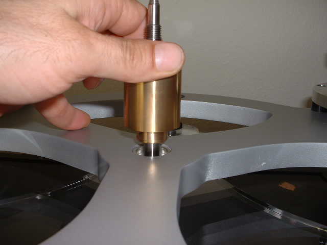
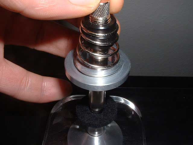
- one inverted main bearing: the aluminium/steel lower part with oil well and shaft, the bronze upper part with sleeve, spindle, and thrust ball
- one phial with synthetic oil
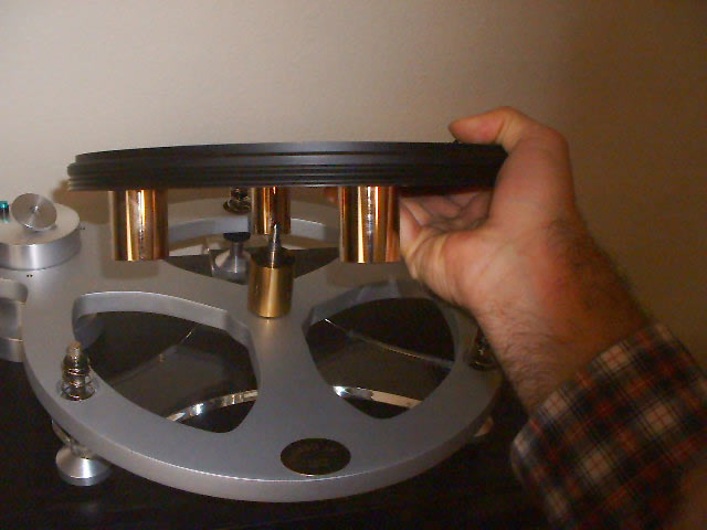
- one platter
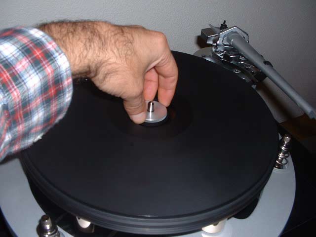
- one platter nut
- one motor, with pulley
- one belt
- one power supply
- one arm adaptor plate (armboard), customised to your tonearm of choice
- three black PVC armboard spacers, three socket screws, one Allen key
- one L-shaped arm clamp (GyroDec only)
- three spring covers
- one record clamp (optional with Gyro SE, but highly recommended)
Assembling the turntable
Take a large and flat surface to spread out the parts, preferrably near to the place where the turntable will be built and then employed. Note that with a mass of near 20 kg, the GyroDec, when finished, may drive its coned feet into any soft surface (like MDF) on which it is resting.
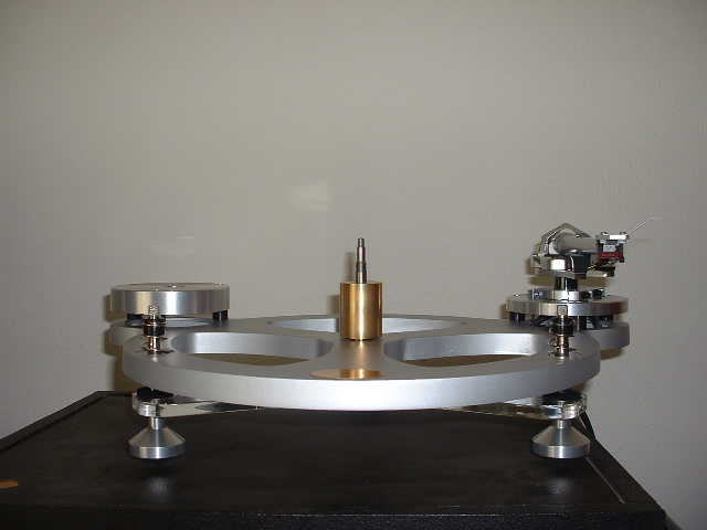
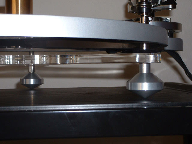
Screw the three standing feet onto the threaded studs on the underside of the base (Gyro SE: underside of the spider). If you can adjust the level of the surface the turntable will be used on, then tighten the three coned feet. Other wise do not tighten yet, as you will use the feet themselves for final levelling.
Screw the spring assemblies onto the threaded spring supports until the knurled parts of the supports are fully showing.
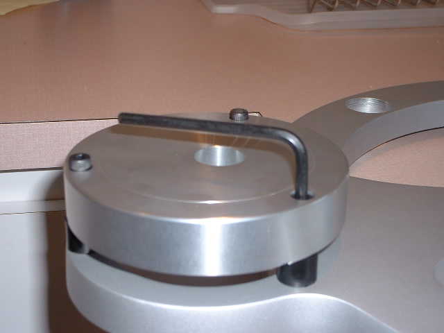
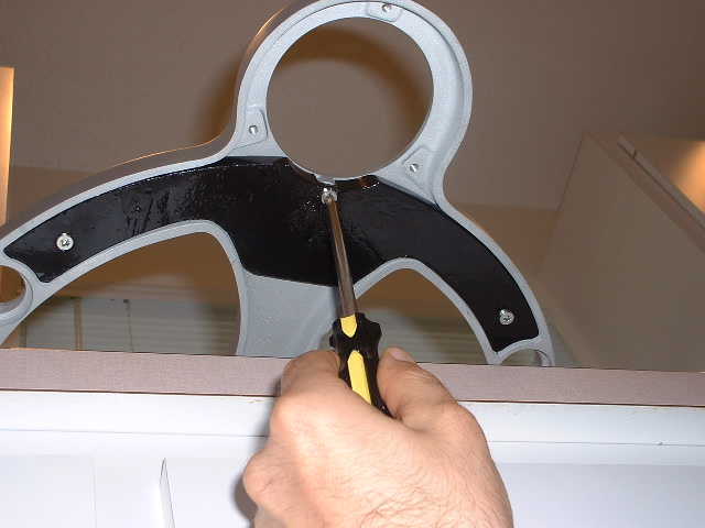
Fit your tonearm, using the correct Arm Adaptor Plate. Mount the plate onto the chassis with the three black spacers and socket screws. A socket key is contained in the package. It is essential that the correct arm adaptor plate be used. Check with your authorized dealer or distributor.
It is also essential that the arm adaptor plate is in the correct orientation with respect to the turntable spindle, so as to obtain the correct overhand. For instance, in the case of our TecnoArm and compatibles such as Rega, the hole in the adaptor plate must be at the maximum distance from the spindle.
Note: for Gyro SE being used with heavy or stiff arm cables such as SME's: one of the three arm adaptor plate screws is supplied longer with a spacer clip and a locking screw. Use this screw at the backside of the arm plate to clamp the tonearm's cable horizontally at the underside of the chassis.
(Note: the picture shows the bearing in place, but the bearing must only be mounted after the subchassis has been lowered onto the springs, see next step.)
Adjusting the suspension
Important note: time spent perfecting this adjustment of the suspension will give optimum sound quality. It is wise to check, and correct, setup again after a few hours, as initially some creep of the spring assemblies may occur.
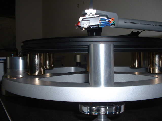
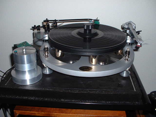
Fit the drive belt around the smaller groove in the motor pulley and in the lower groove in the platter for 33.3rpm. For 45rpm, fit the belt around the larger groove of the motor pulley.
Replace the dust cover.
During the first tens of hours of use the main bearing beds in, and performance improves somewhat. The only part susceptible to wear is the bearing's thrust ball. Therefore it is wise to replace it every five years or so.
A regular light application of quality furniture polish from an aerosol spray will keep the unit and its fittings in pristine condition. Stubborn surface stains can be removed by the careful use of lead free petroleum spirit (proprietary brand lighter fuel) but under no account resort to abrasive polishes as they can remove the surface finish of the acrylic.
Mounting a second arm (Gyro SE only)