INSULATING THIN POLYMER FILMS
|
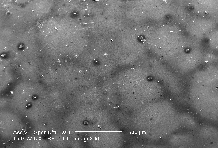
These experiments investigated the compactness and electrical charateristics of silane films on metal surfaces. The experiments were done on an in-house device built specifically for this experiment. The device utilises a spherical stainless steel ball bearing that exerts a force on to the insulating film. The indentations were imaged using a scanning electron microscope. The film was first sputter coated with a thin layer of gold, and then scanned in the microscopes analysis chamber. The figure on the left shows a low-resolution scan of a typical area of the film that contains several indentations within it. Images of two indentations are shown below. Typical diameters of the indentations ranged from 40-60 m m. |
|
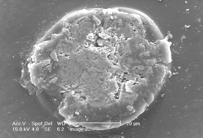 |
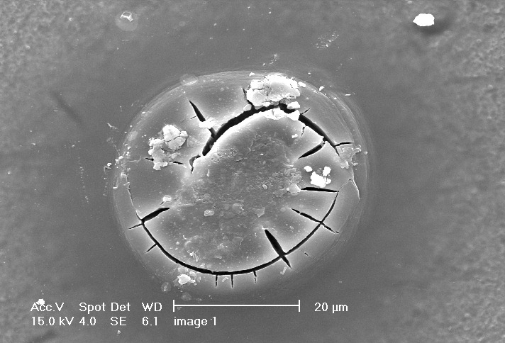
SEM images of Indentations caused by ball probe with a force of approximately 25 N The pictures of the indentations shown here reveal interesting and striking features which show qualities such as hardness, brittleness, plasticity, of the PTMS film. Fully cross-linked organosilanes produce crumbling behaviour under stress when swollen by liquid. This crumbling is observed on the left. The cracking shown in the image on the right indicates a very hard material. |
 |
Electrical Characteristics
 |
 |
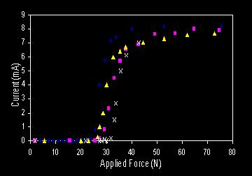
The maximum force exerted by the ball on the film is taken from point B on the graphs, which is centre of the inflexion. The observed maximum force for the film lies between 20.0 ± 0.5 N and 29.1 ± 0.5 N. The error is the difference in force between insulation and conduction. The average maximum force observed was 24.6 ± 4.6N. The pressure experienced by the film from the stainless steel ball can be calculated using
The diameter of the stainless steel ball was measured to be 3.175 ± 0.05 mm using a micrometer. The indentation in the film caused by the ball shown above was measured to be approximately 0.1mm on a sample that had been taken to the breakdown force, but not past it. If the film thickness is taken to be approximately 4 microns from the confocal image below, then breakdown strength can be calculated to be 6MV/m and. Typical dielectric strengths for polymers lie between 5 – 15 MV/m. The resistivity of the PTMS film can be calculated, using a resistance of 18 G W, and an area of 1.96x10 -9 m2 the resistivity is calculated to be 8.84 M W. m. This value of resistivity appears to be a little low when compared with the typical resistivities for silicone containing polymers, which range from 10 8 – 10 12 W m 76. The reduced value od resistivity is most likely to be a consequence of water of hydration still within the film structure. With these characteristics known, the research was then focussed on developing a electromagnetic core from iron powder coated with PTMS thin films. |
|
 |
 |