1. VDO Outside Temperature Kit p/n 397-954 available from egauges
2. Several feet of 16 gauge wire
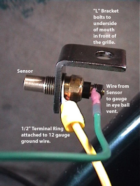
3. A 1/2" Ring Terminal to ground the Sensor
4. Two smaller Ring Terminals to ground the Gauge and the Gauge Light
5. Electrical Tape
6. Wire Stripper/Cutter/Crimper
7. Some Cable Ties
8. Some "Vampire Taps" (they have a metal tab which is squeezed down to cut into the wires being tapped.)
9. A Flat Head Screw Driver
10. A piece of Coat Hanger wire
11. A Rat Tail File
12. Various other odd tools as required
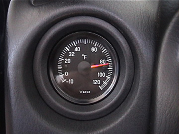
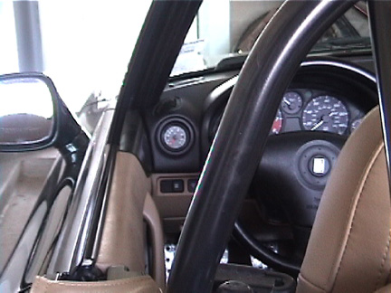
The 2 1/16" VDO Outside Temperature Gauge was installed into the left Heating/Air Conditioning vent.
The eye ball had to be removed first.
To read various methods of removing the eye ball vents, click here.
I was able to remove it by prying it out using a flat head screw driver. The screw driver was pushed about an inch into the space between the dash and the trim ring at the nine o'clock position.
I pushed in about an inch or so to disengage the left hand clip then pried the whole assembly out.
With the assembly out, I separated the trim ring from the assembly by twisting the head of a screw driver into the four slots on the side of the ring. The eye ball fell right out.
You will eventually replace the Gauge for the eye ball then re-attach the trim ring.
The Gauge has five wires attached to it.
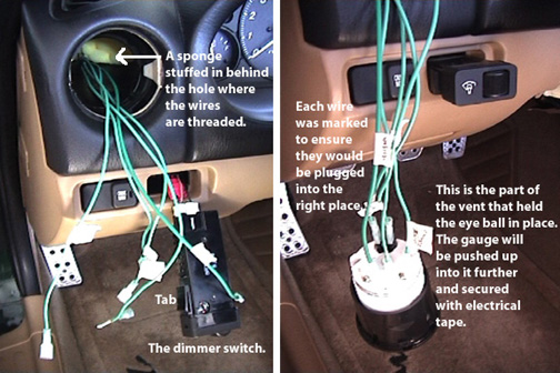
Each of the five wires should be labeled at each end for future reference.
1. LIGHT BULB POWER: I tapped into the Red/Black wire on the "Panel Light Control Switch" using a piece of 16 gauge wire about 18 inches long.
2. LIGHT BULB GROUND: I attached this ground wire along with the Gauge ground wire to a bolt under the dash on a vertical structural member using a piece of 16 gauge wire about 18 inches long.
3. SENSOR: I used the 16 gauge wire provided by VDO.
4. GAUGE POWER: I tapped into the cigarette lighter power wire (yellow) using a piece of 16 gauge wire long enough to reach.
5. GAUGE GROUND: I attached this ground wire along with the Light bulb ground wire to a bolt under the dash on a vertical structural member using a piece of 16 gauge wire about 18 inches long.
Once you have your wires cut to length, you will need to thread them through a hole you've punched in the Heating/Air Conditioning duct.
To make a hole in the exposed heating/air conditioning duct after removing the eye ball assembly, I removed the top knock out panel on the left side of the dash that was revealed by opening the door -- it just pops out using a fingernail or small screw driver.
Looking into the opening of the knock out panel, you will see a metal brace with a round hole in it. The H/AC duct is just on the other side of this hole.
Take a piece of coat hanger and punch a hole in the duct by angling the wire towards the front of the car.
From inside the car, through the vent opening, you can then ream the hole large enough to work a rat tail file into it so that you can enlarge it into an oval shape.
This will allow you room enough to thread the five wires described above through it and under the dash as seen here:
Note: To remove the dimmer switch (as seen above), you must reach under the dash and squeeze the "tabs" on each side of the switch and push the switch out. Remove the plate under the steering wheel first (two philips head screws) to access the switch.
First, connect the sender and ground wires to the Sensor and attach it to the "L" bracket as seen here:
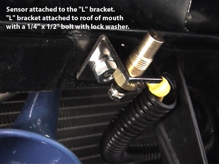
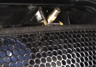
Then, attach the Sensor itself in the mouth of the car using the supplied "L" bracket as seen here:
Next, thread the Sensor wire and the Ground wire up into the engine bay.
I have a grille which I reinstalled as seen here: (the Sensor fits right over the top of the grille.)
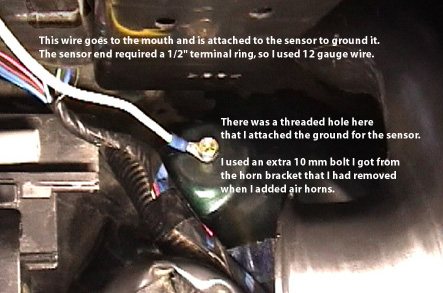
Find a place to ground the Sensor to the car chassis as seen here: (you may find an alternate place for the ground.)
Then, thread the Sensor wire (it's 10 feet long) over to the firewall where you will pull it through the grommet described below and into the interior footwell.
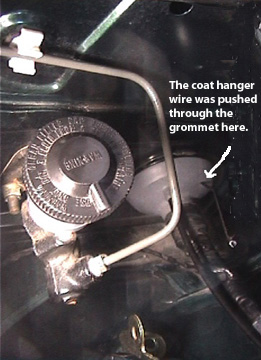
To thread the Sensor wire from the engine bay into the interior footwell of the car, push a coat hanger wire through the large gray grommet in fire wall. The grommet is located on the firewall on the driver's side and is about 3 inches in diameter and can be seen here:
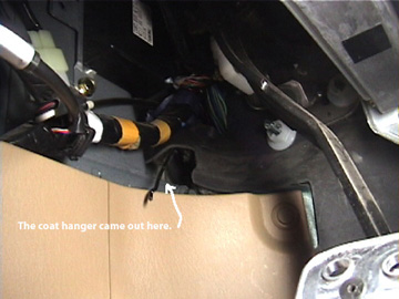
Here is where the coat hanger came out into the footwell:
Attach the Sensor wire to the end of the coat hanger in the engine bay and pull it through the grommet into the foot well under the dash from inside the car.
From inside the car, push a piece of coat hanger through the hole in the H/AC duct and into the area under the dash.
Attach the Sensor wire that is in the foot well to this coat hanger wire and pull the coat hanger wire with the sensor wire attached through the hole in the H/AC vent and into the car.
Discard the eye ball.
Discard the screw-on piece that came with the gauge.
Put the gauge into the eye ball assembly.
Re-attach the trim ring.
You will observe that the gauge face needs to be secured against the inside of the trim ring. Turn the assembly upside down on a soft cloth on a table.
Center the back end of the gauge in the assembly with equal space all around.
Then be sure that the gauge is facing up right -- use the indentions on the side of the assembly as reference points. They should face 3 and 9 o'clock. The top of the gauge should face 12 o'clock.
At this point, you will need to secure the gauge firmly in the assembly.
I used short pieces of electrical tape to hold it in place.
I then wrapped electrical tape around the circumferance of the gauge being careful not to cover up the indentions on the sides of the assembly.
Finally, I inserted one inch wide pieces of mat board around the edges between the gauge and the assembly to act a shims.
Connect the five wires to their appropriate places on the back of the gauge -- the instructions that came with the gauge has a diagram to follow.
Turn the ignition to ACC.
Hopefully the gauge needle will spin over and register the temperature.
Check for illumination.
If everything appears to be working correctly, pull the excess wire into the underside of the dash through the hole you punched in the H/AC vent.
Then push the eye ball vent containing the Outside Temperature Gauge into the vent opening.
. . . . . . . . . . . . . . . . . .
If I can add any further information, please email me.
