Also used in models 101, 110, 111 and 301.
To further complicate things, there are actually two main versions of the "tubeless" type of Equasonne selector. The "tubeless" selector from the model 931 shown here was the version used in later models. Earlier models contained a very similar looking but slightly different (930 type) unit. These two tuners really only differ from each other in two small details. The earlier 930 and later 931 "tubless" tuners are fully interchangeable.
The RF amplifier circuits of the equasonne cannot be aligned as can those of many TRF radios, as they are untuned. It is however possible to make minor adjustments to the antenna compensating and equalizing condensers.
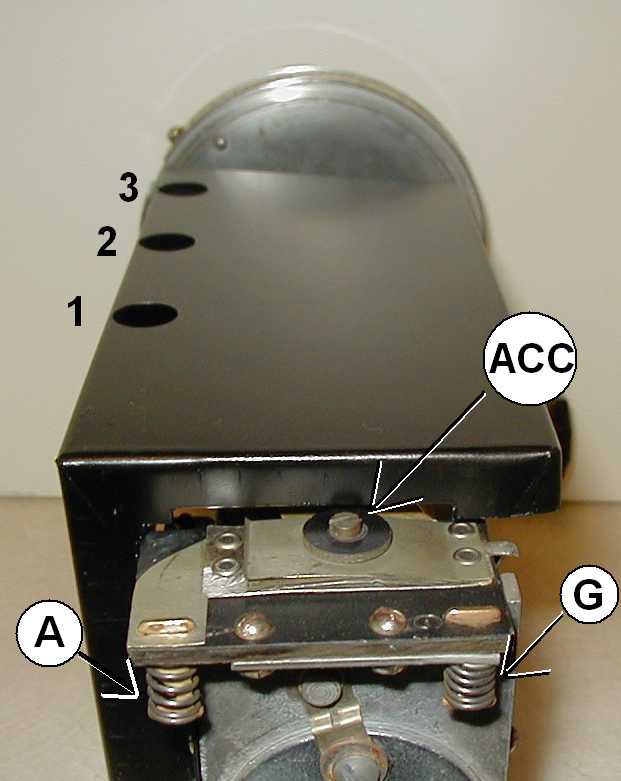
The Antenna compensating condenser which can be adjusted with a flat head screwdriver until maximum signal strength is achieved is indicated (ACC).
The three equalizing condensers are not visible with the upper shielding installed. The adjusting nuts are accessible through the 3 access holes in the top of the shielding. These condensers are numbered 1 thru 3, with number 1 being the farthest from the tuning drum. Adjust condenser 3 first, then 1, and finally 2.
Instructions on adjusting all four of these trimmer condensers is given elsewhere in this website.
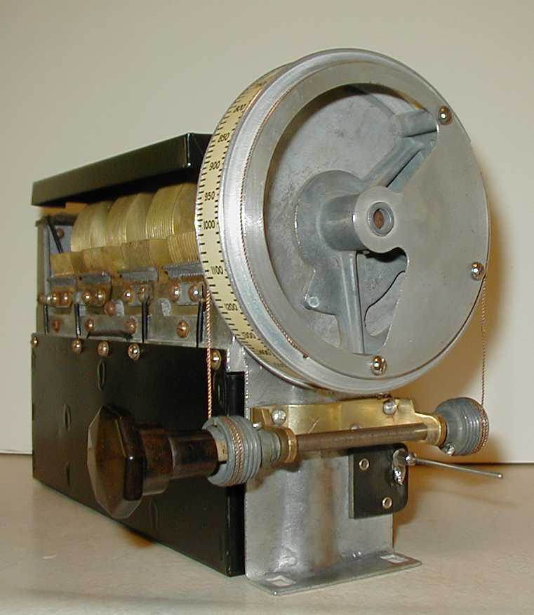
The original plastic scale on the tuning drum may have become very fragile over time. If it is broken or needs replacing, a reproduction scale can be obtained from Rock Sea Enterprises. The dial scale used in the all the Equasonne models described on this website are the same (Sparton part no. A-4584). The dial lamp that sits inside the drum is actually part of the RF amplifier unit.
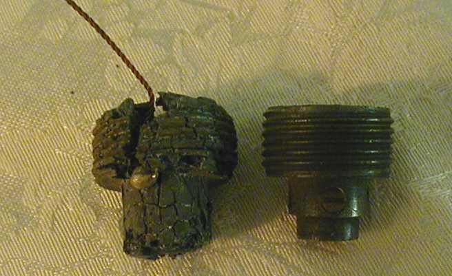
The selector unit contains a few pot metal castings. Pot metal is notorious, and generally ages very badly, becoming incredibly fragile and often puffing up and splitting like popcorn in the process. In the radios I have come across, the castings generally seem to age well, however I do have one tuner where the two threaded spools that take up the dial cord have puffed up and cracked so much as to become unusable.
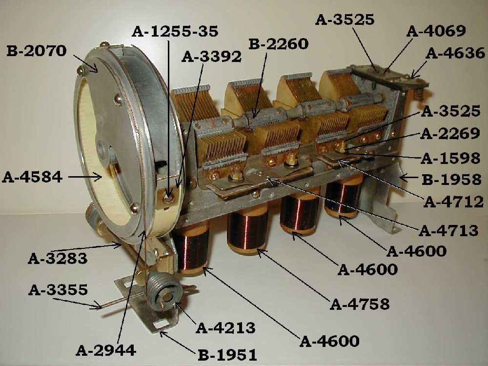
Generally a good cleaning seems to be in order with these selector units. The bottom shielding box that encases the coils tends to serve as an excellent home for all sorts of fauna! Be very careful when removing the botton shielding box, so as not to touch or scratch the fine wire on the 4 coupling coils inside. Unsolder the connector wire that protrudes through the shielding to the long connector prong before removing this shielding.
A description of how to adjust the antenna compensating and equalizing condensors on the selector unit is given elsewhere on this site.