Presetting of Tools: Tool length determines tool travel when tool is fed into the work for machining. Tool length and tool diameter have to be exactly known to program the instruction. Measurement or calibration of these parameters is done by optical tool pre setter or a special fixture in which the tool along with its holder (collet and chuck) could be located. Tool tip from a specific point on the collet (which goes into the spindle of the machine), could be calibrated by means of a micrometer mounted on a calibrated stand. Every time a tool is replaced it is calibrated and the information (tool length and diameter) is recorded on a tool card which is ten used when calculating compensations/offsets. Such information is essential for reducing machine set up time.
The
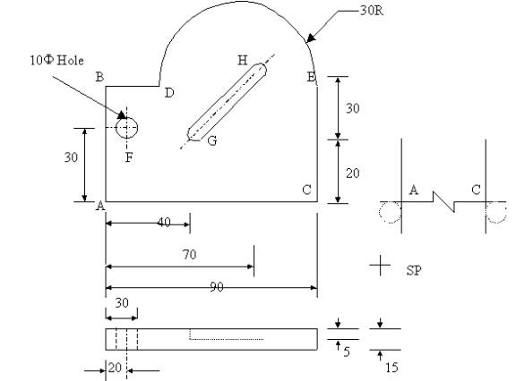
operations to be done on the job are:
a) The edge ABDEC is to be machined. For this a 16mm diameter-milling cutter will be chosen. (Tool no 1)
b) A hole is to be drilled at F (Tool No 2: 10mm drill)
c)
A slot 14mm wide and 5mm
deep is to be cut from G to H (Tool
No 3; 14 mm slot drill)
Radius
Offset: Let us take the example of machining of
edge AC. For this, cutter under shoot or overshoot is used. The program will be
written as if the cutter center moves along the path AC, the radius offset will
be put into the offset switch manually (say No 1) . Such feature can only be
used while machining along X or Y-axes. It is called by Q word address namely
Q0001, Q0002, etc. (The first two digits are for length compensation while last
two digits are for radius compensation). It can be cancelled by address Q-- 00.
Tool length offset: This is to be provided when number of tools are used. In this case pre-set tools are used. The offset values (equal to difference in lengths of tools) when dialed in appropriate offset switches make the system behave as if all the tools are of equal length. This is called into operation by program instruction Q0100, Q0200, etc and cancelled as earlier by Q00--.
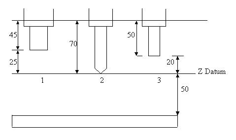
To use this feature, work piece is set with the longest tool (in this case 10 dia.drill (tool2) has been shown as set at 50mm above the work). The difference in lengths of other tools with respect to longest tool (i.e., 25mm for tool no 1 and 20mm for no 3) are entered in length-offset switches (no.1 and no.3 respectively, zero being entered in switch no 2). Then, in the program when Q0100 and Q0300 are read, the Z travel of tools 1 and 3 are accordingly modified, thereby all the tools behave as if their lengths are same.
Program:
N001 G92 X0 Y0 Z0
N002 G90
N003 G42 X0 Y0 Z-68000 R-48000 Q0101 F0 M03
N004 G41 X90000 F100
N005 G41 Y50000
N006 G40 Q0100
N007 G03 X22000 Y58000 I-38000 J0
N008 G01 X-8000
N009 G01 Y-8000
N010 Z0 F0 Q0000 M05
N011 G81 X20000 Y30000 Z-68000 R-48000 Q0200 F300 M03
N012 G80 Z0 F0 Q0000 M05
N013 G78 X40000 Y20000 Z-55000 R-48000 Q0300 F200 M03
N014 G01 G79 X70000 Y50000]
N015 G80 Z0 F0 Q0000 M05