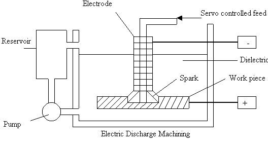
Electric Discharge
Machining
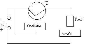
Welding is joining process in which metals first melt then solidify forming a joint. In the process if molten metal can be continuously removed, separation will result; this principle is used in electric discharge machining. This process of material removal by controlled erosion through a series of electric sparks was first started in USSR around 1943. Electric Discharge Machining is a process of metal removal from a conducting work piece by a repetitive spark discharge initiated between negative tool and positive work piece separated by a dielectric medium. Thus the process makes use of electric energy to cut metal to desired shape. This is also called spark erosion or Spark Machining Process. Electric energy for creating discharge is stored in a capacitor: thus the process is called electric discharge machining. No chips are produced in the process and the work piece and electrode (tool) both are immersed into the dielectric fluid.
Suitable gap (Spark Gap is maintained between tool (electrode) and work piece. Tool (cathode) and work piece (anode) are separated by dielectric fluid. Generally spark gap is about 0.005 to 0.05 mm long. Dielectric fluid is non- conductor of electricity in normal conditions. But at suitable voltage (50 to 450V) it breaks up into ions. Controlling of electric discharges across the electrode and work piece controls erosion of work piece material. Dielectric medium helps in initiating discharge by serving as a conducting medium when ionized and conveys spark. It also acts a s coolant and helps in removal of micro metal particles.
RC Relaxation Circuit For EDM
t1 = charging time & t2 = spark time
Voltage applied across capacitor and as it is charged, voltage across the capacitor rises. At sufficiently large voltage, say V, dielectric medium breaks up due to development of a strong electrostatic field between he electrodes. The dielectric medium gets ionized and the spark takes place. Millions of electrons are released during the spark and they travel towards the work piece. Electric and magnetic fields are also developed during the spark.
Compression shock waves are generated. Temperature of the order of 10,000 ° C is reached at the spots hit by the electrons. At such high temperature metal is melted and eroded. During spark period voltage immediately falls and rises. The sparks are made to discharge at a high frequency with a suitable source. The spark occurs at the spot where the tool and work piece are closest and since material is removed after each spark the spark spot changes after each spark and the spark travels over the surface. This results in a uniform material removal all over the surface and finally the work face conforms to tool surface. The spark frequency is normally in the range of 200 to 500,000Hz. A material removal rate up to 300mm3/min can be obtained.
With this process intricate shapes of any metals or alloys can be produced irrespective of their hardness and toughness. Main limitations of he process are: metallurgical properties of the metals change during the process, machining of complicated profiles is difficult and specific power consumption is high. Extrusion dies, forging dies, intricate mold cavities and sometimes carbide tools are made with the process.
Current density in discharge channel: 10,000 A / cm 2
Power Density: 500 MW/ cm 2
Electro hydraulic servo control is used to actuate the tool and adjust required distance between the tool and work piece. Input signal from difference between a selected reference voltage and actual voltage across the gap is amplified and used to actuate the tool. As the gap increases the tool is advanced by required distance by hydraulic control. A short circuit across the gap causes the servo to reverse the motion of the tool until the correct gap is established.
The rate of material removal from cathode is comparatively less than that from the anode due to following reasons:
Over- cut: Area of the cavity produced in the work piece should be equal and similar to the area of the tool but in actual practice the radius of the cavity in the work piece is slightly larger than the radius of the tool nose and also radius of the projection on the work piece is slightly lesser than the radius of the cavity of tool. This is due to Over-cut. It is the distance the spark penetrates the work piece from the tool and removes metal from the work piece. It is dependent on the spark length to some extent on the crater dimensions. Theoretically it is slightly larger than the gap between end of the tool and work piece. It ranges from 0.025 to 0.2 mm. Over-cut causes internal corners on the work piece to have fillets with radii equal to the over-cut. In other words an over cut is that dimension by which the hole in the work piece exceeds the electrode size. Over-cut increases with higher current and decreases with higher frequency.
Material
Removal Rate Calculations:
Material Removal Rate (MRR): It is defined as the volume of material removed per unit time. MRR is proportional to working current value. Also it depends on material being cut. Experiments indicate that it varies inversely as the melting point of the work piece material. An approximate relationship for getting a rough estimate of material removal rate (mrr) under normal working conditions is in terms of the melting point of the work piece material and is given by
Q = 4 x 10 4 qm –1. 23 mm3/amp-min
(qm is melting temperature in °C)
This relation assumes average sparking condition. The mrr also depends upon the circulation of the dielectric fluid. Without a forced circulation the wear particles repeatedly melt and reunite with the electrode
Electrode (Tool):
Shape of the tool will be basically same as that of the product desired except that an allowance is made for side clearance and over-cut. For small holes, solid rods are used and for larger ones hollow tools are used. Dielectric is pumped through the hollow tool.. Three types of materials are used in making tools
Metals (alloys) like copper, yellow brass, zinc, silver tungsten, and copper tungsten and metallized graphite.
Non-metallic materials like graphite.
Materials with metallic as well as non-metallic constituents like copper graphite.
For commercial, fine machining applications copper is most suitable. Aluminium is useful in die sinking applications and cast iron tools are used for rough machining. The advantage of EDM process is that materials softer than the work piece can be used as machining tool.
EDM
Circuits and Operating Principles:
Types of circuits used in EDM can be classified into three groups:
1) Resistance – Capacitance (RC) relaxation circuit with a constant dc source.
2) Rotary Impulse Generator
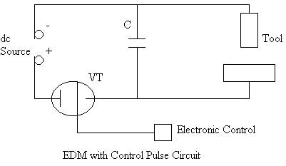
3) Controlled Pulse Circuit
The capacitor is charge through a variable resistance R by the dc source of voltage V0. The voltage across the gap (which is almost same as the voltage across the capacitor) V varies with time according to relation
V = V0 (1-e –t/RC) where t denotes the time starting at the instant V0 is applied.
When the voltage across the gap reaches a value Vd (discharge voltage), a spark will occur discharging the capacitor completely. The discharge time is much smaller (about 10 % of the charging time) and the frequency of spark (f) is approximately given by the following equation :
f = 1/tc = ________1___________
RC loge [ V0 / (V0-Vd)]
Here, tc = charging time which is equal to the time required for the gap voltage to reach a value Vd
The energy released per spark is given by E = 0.5 (C Vd2)
![]()
The average value of power delivered P av = E / (tc + td), td is the time of discharge.
If we assume the material removed per spark to be proportional to the energy released per spark, then the mrr can be expressed as
![]() Q
= K 0.5 (C Vd2) f
Q
= K 0.5 (C Vd2) f
Where K is the constant of proportionality denoting the fraction of power effectively used in material removal.
In case of machining steels under normal conditions, the removal rate can be approximately expressed as:
Q = 27.4 W 1. 54 where Q is the removal rate in mm3/min and W is the power input kw.
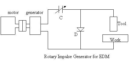
Rotary Impulse Generator: MRR is not high in case of RC relaxation circuit. To increase mrr impulse generator is used. The capacitor C is charged through the diode during the first half of the cycle and during the following half the sum of the voltages generated by the generator and the charged capacitor is applied to the work – tool gap.. The operating frequency is the sine wave frequency that depends on motor speed. Though the mrr is higher surface finish is not good.
Controlled Pulse Circuits: This circuit has provision for automatic prevention of current flow when short circuit is developed. For such automatic control a vacuum tube ( or a transistor ) is used as switching device. During spark the current flowing through the gap comes from the capacitor. When the current flows through the gap the valve tube (VT) is biased to cut off and behaves like an infinite resistance. The bias control is done through an electronic control (EC). As soon as the current in the gap ceases the conductivity of the tube increases allowing the flow of current to charge the capacitor for next cycle.
The circuit can be simplified and stability can be improved if flow of current is allowed cyclically with an imposed frequency. This can be controlling the bias with an oscillator. In this case the capacitor is not needed
EDM with controlled pulse circuit without capacitor
Tool wear due to ions and electron- bombardment is inevitable. Tool wear affects surface finish, metal removal rate and production rate. Also tool wear influences machining accuracy, tool movement and tool consumption.
Tool wear is function of metal removal rate, material of work piece, current, machining area and the gap between tool & work piece. Tools made of materials with higher melting point wear less.
Wear Ratio = volume of work material removed/ volume of electrode consumed
= Depth of cut / decrease in usable length of electrode
Wear Ratios of some materials (While machining steel)
|
Material |
Wear Ratio |
|
Carbon |
100: 1 |
|
Copper |
2: 1 |
|
Brass |
1: 1 |
|
Copper Tungsten |
8: 1 |
Surface Finish in EDM:
Material removal in EDM is achieved through the formation of craters due to the sparks, it is obvious that large crater sizes result in rough surface. Crater size mainly depends on energy per spark. The forced circulation of dielectric has been found to generally improve the surface finish.
Dielectric
fluid:
Characteristics:
1.It should be a non-conductor of electricity under normal conditions unless excited by suitable voltage.
2. It should also act as coolant.
3.It should have good flowability and should be able to carry away suspended metal particles from the gap.
4. It should be cheap and available easily.
5. It should be able to quench the spark and deionize it after discharge occurs.
Common fluids used as dielectric medium in EDM:
Kerosene, paraffin, transformer oil and tetra ethylene glycol. Water acts as a conductor when it is impure, so with it use, as dielectric medium a material removal rate of only 40 % of that achieved with paraffin is possible.
Accuracy :
Normally a tolerance value of ± 0.05 mm can be achieved in EDM. With close control of several parameters a tolerance of ± 0.003 mm can be attained.
Application of EDM
It is used to manufacture tools of complicated profiles and number of components. Stamping tools, wire drawing and extrusion dies, header dies, forging dies, and intricate mold cavities are economically made by the process.
Typical
EDM applications include:
Fine cutting with thread shaped electrode.
Drilling of micro holes.
Thread cutting.
Helical Profile Milling.
Rotary Forming.
Curved hole drilling.
Disadvantages
: