Electrochemical Machining is one
of the most effective unconventional machining processes. It can be considered
as a process quite similar to reverse of electroplating with some modifications.
Electricity conduction through metals involve movement of electrons whereas in
electrolyte electricity is conducted by motion of ions and ions have mass. Thus
conduction via electrolyte involves movement of mass. This principle is used to
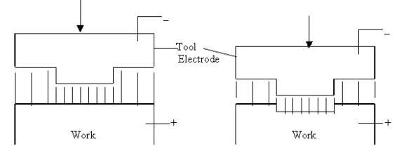
remove mass from an electrode during ECM process. Work piece is connected to
anode and the tool to the cathode and the gap between the two is filled with
electrolyte or rather the electrolyte is pumped through the gap. The anode
starts to dissolve as current is passed through the cell. Rate of dissolution is
more if the gap between the tool and work piece is smaller. If the tool is given
downward motion, work surface tends to take same shape as the tool. Tool is
given a constant feed motion.
Scheme of Electrochemical Machining
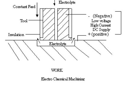
Generally
electrolyte is pumped at high pressure through the tool and the gap between the
tool and work piece. The essential condition for ECM is that anode should be
dissolved without any deposition at cathode. Current passed through the set-up
is in range of few thousand amperes and the voltage in the range of 8-20 V. The
gap measures about 0.1 to 0.2 mm. Material removal takes place at a rate of
about 1600 mm3/min for 1000amp. One remarkable advantage of the
process is that the mrr is independent of work material hardness. Any
complicated profile can be machined on the work piece with this process. And
above all there is no tool wear in the process. Tool and work are subjected to
high pressure of the electrolyte fluid flowing across the gap. Besides that no
other force acts on the tool (of course the feed force will be there).
Area of tool
where electrochemical machining is not desires is insulated to minimize astray
(unwanted) machining. Insulation in form of reinforced solid plastic or
synthetic rubber should be securely bonded to tool surface with either epoxy
resin cement or plastic screws. Boundary of insulation should not be subjected
to high velocity electrolyte flow that may tend to tear the glued layer of
insulator.
Electrochemistry
of the process:
Electrolysis
process is governed by following laws of Faraday:
so,
mathematically ,
m a It
And also
m a e
So,
m a
It e
Here m is the mass of material deposited or dissolved in gm.
I is current in ampere.
e is the gram equivalent weight of the material.
t is time in seconds
Introducing Faraday's Constant (F) in above equation we get following relation:
m
= (I t e)
/ F
F = 96,500 Coulomb, and it is amount of charge required to deposit 1gm equivalent of any material:
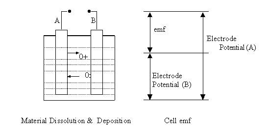
When any metallic body is submerged in an electrolyte, metallic atoms leave the body to become ions and some ions may enter the body to become atoms. Thus the point on surface of metallic body and the adjacent point in the electrolyte have a potential difference and this potential difference is known as electrode potential.
In case of iron (Fe) and Copper (Cu) electrodes dipped in NaCl solution:
Fe « Fe 2+ + 2e - (-0.409 V)
Cu« Cu 2+ + 2e- (+ 0.304V)
Difference between the electrode potential is : 0.304- (- 0.409) = 0.713 V.
Electrode
potential value depends on electrode –electrolyte pair. If A and B are two
electrodes submerged in an electrolyte and the electrode potentials of A and B
are VA and VB then
the emf of the cell will be equal to difference between the electrode potentials
i.e. VA - VB.
Let
us consider the case of Fe and Cu inserted into NaCl solution. Fe is connected
to the anode and Cu is connected to the cathode.
At
anode:
Fe ®
Fe ++ +
2e-
At
cathode: H2O
+ 2e-
®
H2
+ 2 (OH)-
Fe ++ ions will be attracted towards the cathode (copper electrode) and (OH)- ions will be attracted towards anode. Following reaction will take place between these ions:
Fe ++ + 2
(OH)- ®
Fe (OH)2
Electrolyte
selection should be such that there is no deposition at either electrode.
e = A / Z = Atomic Weight / valency of the ion produced
Thus
recalling the relation we have derived above:
m = (I t e) / F can be rewritten as :
m
= I t A / F Z
or
, m /t = IA / FZ gm
/sec
Material
Removal Rate Calculation in Case of Alloys:
Let
us consider a case of an alloy made of number of constituents with atomic
weights A1, A2, A3, A4…. An and
valencies of their ions be Z1, Z2, Z3,Z4……..Zn
and their proportions in the alloy be x1 % , x2% x3%
x4% ……xn% respectively.
Let r
be the overall density of the alloy. And V be the total volume of the alloy.
Amount of constituent 1 in the alloy is (rV x1 / 100) gm.
Similarly amount of constituent 2 in the alloy is (rV x2 / 100) gm.
Charge required to deposit/dissolve all of constituent 1 from the alloy is:
![]()
Therefore, total charge required to dissolve out all constituents from the alloy is:
![]()
So volume removed or dissolved per unit charge =
![]()
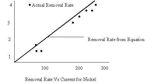
Material removal rate during ECM is affected by many factors. Some metals have more than one valence states. For example nickel ions can have valency 2 or valency 3. When current is low nickel dissolves in divalent form while on larger current supply nickel starts to dissolve in trivalent state. The rate of dissolution (gm/sec or mm3/sec) will decrease with increase of dissolution valency. Sometimes the dissolution valency also depends on the type of electrolyte being used. For example copper is monovalent in chloride solution and divalent in nitrate solution.
|
Metal |
Gram
Atomic Wt |
Valency
of Dissolution |
Density (gm/cm3) |
|
Aluminium |
26.97 |
3 |
2.67 |
|
Chromium |
51.99 |
2/3/6 |
7.19 |
|
Cobalt |
58.93 |
2/3 |
8.85 |
|
Copper |
63.57 |
1/2 |
8.96 |
|
Iron |
55.85 |
2/3 |
7.86 |
|
Nickel |
58.71 |
2/3 |
8.9 |
|
Tin |
118.69 |
2/4 |
7.3 |
|
Titanium |
47.9 |
3/4 |
4.51 |
|
Tungsten |
183.85 |
6/8 |
19.3 |
|
Zinc |
65.37 |
2 |
7.13 |
|
Silicon |
28.09 |
4 |
2.33 |
|
Manganese |
54.94 |
2/4/6/7 |
7.43 |
Electrolyte conductivity changes as the electrolyte passes through the gap due to :
a) Increase in its temperature
b) Hydrogen Bubbles Formation
c)
Formation of Precipitates
Surface
Finish in ECM:
Generally the
surface finish in ECM is good as the machining process doesn't involve direct
contact between tool and work piece. But there are some factors that are likely
to affect the surface finish:
i) Selective Dissolution
ii) Sporadic Breakdown of Anodic Film
iii) Separation of Flow and Formation of Eddies
iv)
Evolution of H2 gases.
Selective
Dissolution: The alloy constituents have different electrode
potential. In a single work piece there may be two constituents A and B such
that VdB > VdA ; electrode potential of B is greater
than the electrode potential of A . But during the process the whole anode
surface is equipotent. Thus to create required VdB , parts of
constituents of B will protrude out of the anode. This results in surface
roughness.
Sporadic
Breakdown of Anodic Film: This is due to
gradual fall in potential difference between work surface and electrolyte in the
region away from the machining area.
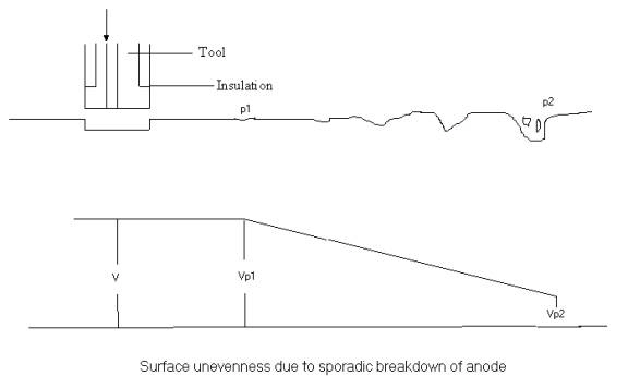
At point
P1 the voltage Vp1 is below the dissolution potential of one phase. Voltage goes
on decreasing along the distance away from the machining area and increasing
number of phases stop dissolving. This also results on concentration of electric
field in small proportions of the anode surface. As a result phases dissolve
very rapidly and pits are formed on the surface. Beyond P2 no dissolution
occurs.
Flow Separation & Formation
of Eddies:
Presence of hills and valleys on anode surface causes separation
of electrolyte flow and eddies are formed. These eddies separate from main flow
and bring about large concentration of metal ions at some areas near the
electrode surface. High concentration overpotentials caused in the eddies result
in localized variations in removal rates and the surface becomes uneven.
Hydrogen
Gas Evolution: Hydrogen gas in
electrolyte reduces conductivity of the solution. The conductivity decreases
along downstream and results in deterioration of surface finish.
Electrolyte in ECM process serves following functions:
a) Completing the electric circuit and allowing a high current to pass.
b) Sustaining required electrochemical reactions.
c) Continuous dissolution of anode and no material deposition at the cathode.
The cationic constituents of common electrolyte used in ECM process are: Ammonia, alkali metals or hydrogen. Besides, electrolyte should have good chemical stability, inexpensive, safe and non-corrosive.
Types of Electrolytes
(Ref: Ghosh & Mallik)
|
Alloys |
Electrolyte |
|
Iron Based |
Chloride Solution in water (20% NaCl) |
|
Ni Based |
HCl or Mixture of Brine & Salt |
|
Ti Based |
10% HF + 10% HCl + 10% HNO3 |
|
Co-Cr-W Based |
Nacl |
|
WC Based |
Strong Alkaline Solution |
Effects
of ECM on material properties:
This process is a smooth and
gentle one. Residual compressive
stress on the surface is low. Depth of work hardened surface layer is negligible
about 0.001mm compared to 0.5- 1.5 mm in turning and milling operations.
Magnitude of residual stress on the surface machined by ECM is almost zero while
that on the surfaces machined by conventional processes is 50 Kg/cm2.
The fatigue strength of parts produced by ECM is however low. Additional
processes like mechanical polishing, vapor blasting or glass bead blasting can
be used to enhance the fatigue strength of ECM products.
Summary
of ECM Characteristics:
Mechanics of Material Removal : Electrolysis
Medium :
Conducting Electrolyte
Tool Materials:
Cu, brass, steel
Material Removal to tool wear ratio: Infinity
Gap
50-300 mm
Maximum Material Removal Rate 15 x 10 3 mm3/min
Specific Power Consumption
7 W/mm3/min
Critical Parameters Voltage, current, feed rate, electrolyte,
electrolyte conductivity
Materials Application
All conducting materials and alloys
Shape Application Blind Complex Cavities, curved surfaces, through
cutting, large through cavities
Limitations High Specific Energy Consumption (150 times that
required in conventional machining), not applicable
for non-conductors and for small jobs, expensive.