The structural design of 750 East Pratt as a unified system essentially involved starting the design from step one. I attempted to envision the design concepts of the original structure and implement them in my own as they were advantageous to my alterations. Through careful examination of the materials supplied to me, I validated several assumptions in order to create an accurate model of the redesigned building. The process I created was iterative and four-fold. It includes alterations of the initial design situation (in order to optimize and unify the structural and architectural designs), initialization of the design process (in which I decided on a preliminary system based on general requirements), optimization of the system which resulted from that initialization, and analysis of that system in order to show the improvements possible to the overall system of 750 East Pratt from the original.
a. Alterations: General Consideration
Simplification of the building system and structural plan was taken to the most literal interpretation possible. Considering the architectural and structural requirements of the building simultaneously, an optimized plan and grid was conceived. Symmetry was followed to the extent that the site, safety requirements, and structural practicality allowed. An altered column layout was key in this redesign, and allowed the more uniform bays which ultimately led to more uniform load distribution and member sizes. Elevator and stairwell shafts were relocated to accommodate these changes. See the Architectural System Design section for a more detailed explanation.
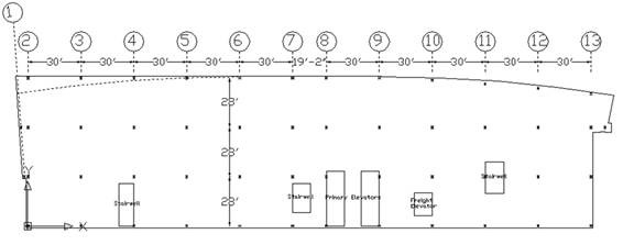 |
| Typical Altered Column Grid Layout: Level 6 |
b. Initialization: Floor System Consideration
The decision of whether to redesign 750 East Pratt in concrete (similar to the substation construction), or steel (similar to the tower construction), was based initially upon the type of floor system which could most consistently and most effectively handle the relatively low gravity loads of the office levels as well as the higher and more dynamic loads of the electrical substation equipment and vehicular traffic.
The effectiveness of such a floor system is essential. On the office floors, where people spend their days and the operation of sensitive computer equipment must be considered, vibration is a key issue. Substantially larger loading conditions exist in the substation equipment rooms and must be accounted for. The diaphragm action of the floor system must also be preserved for lateral efficiency.
Consistency is desirable so that constructability and simplicity may be achieved. Although different floor systems might be ideal for different situations, the most desirable system in this case would be one that could effectively handle BOTH the low and high loading cases without being over conservative in any situation.
Floor system alternatives were considered for both concrete and steel superstructures. Calculations further supporting these results are tabulated in my preliminary reports.
- i. Concrete System Alternatives:
- Two concrete floor systems are well known for handling large point and dynamic loads: the waffle slab system and the post-tensioned beam system. The disadvantage that both of these systems has is inflexibility. Neither allows flexibility with penetration location, or is easily altered after construction, should future tenant requirements demand it. In a generic open plan office building, flexibility is important to the rentability of the space. The strength of these systems is not necessary or economical for the loading conditions of the office levels. Concrete as a whole does not offer the flexibility required for the specific requirements that 750 East Pratt poses.
- ii. Steel System Alternatives:
- Two steel floor systems were also considered for this building's needs. The original composite deck on W-shape beams was an obvious consideration, as was an alteration substituting open web joists for the W-shapes. Open web joists offer a lower strength-to-weight ratio than traditional W-shapes, but after researching several cases involving these joists, I decided against implementing them in my design. Open web joists are difficult to fireproof, and tend to be deeper than W-shape members with similar structural properties. Open web joists offer considerable advantages in extremely tall buildings where every pound counts, but in a 20-story office building these benefits did not outweigh the disadvantages.
The redesign of 750 East Pratt will be attempted with the use of W-shape steel beams supporting composite steel decking. A composite system, while more expensive, also reduces member sizes as compared with a non-composite steel system.
Note - Concrete floor systems may pose an advantage if the plenum depth cannot be retained through the use of composite deck and W-shape beams. If this is a problem, a concrete system may be the only alternative. Optimization of the lateral system should avoid this problem.
c. Optimization: Lateral System Consideration
The lateral force resisting system in a steel-framed building generally consists of rigid moment frames, pinned braced frames, or a combination of the two. All three of these alternatives were explored within the limitations of the architecture and the structural plan of the building and are described on the following page.
Each of these systems was modeled in RAM Modeler utilizing the following assumptions.
- a1. Design According to AISC LRFD
- a2. P-Delta Effects Included
- a3. Rigid Diaphragm Effects Included
- a4. Dual-System Effects Considered In E-W Direction
- a5. Building Considered Sidesway Inhibited
Three cases are illustrated here and described below.
-
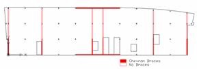
Braced Framing Layout - The braced frame system was the most rigid in layout, as the braces will interrupt the open office layout if they are not adjacent to either the core or exterior walls. Braces were located where they would be least obstructive to the architectural functions of the building. See note below regarding brace selection.
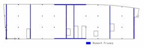
Moment Framing Layout - The rigid moment frame system was much more flexible in layout, and so the number and placement of moment frames necessary to optimize the design could be iterated through trial and error using the RAM Frame software for comparison purposes.
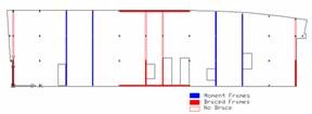
Combination Framing Layout The combination braced-moment frame system is one that utilizes the most effective qualities of both above systems. Using the results and assumptions described below, an optimized combination of the two systems was designed.
Note - Initially, four braced frames and two fixed moment frames resisted lateral forces in the E-W direction (similar in orientation to the braced and moment framing layouts shown above), but after checking for strength and deflection, two additional moment frames were added, leading to the final design.
Note - A preliminary comparison of chevron, V-, and X-braces was performed in STAAD to estimate what type of brace would be most effective in this case. Chevron braces were found to be the most efficient in that they reduced drift while reducing the effective length (and thereby increasing the effectiveness) of the lateral girders that they supported. Knee braces were used in place of chevron braces where window obstruction would be undesirable. The results of this comparison are tabulated in Appendix E.
- i. Braced Frame System
- The braced frame system was modeled in RAM as shown. Due to the open plan architecture of the office levels, braces could only be implemented where shown graphically above. The braces at grid lines 4 and 11 may be objectionable to the owner as well, but were included as a possibility for optimization. Regardless, no column size up to W14 satisfied the gravity loading conditions of the building. The gravity columns must carry proportionally higher loads because the pinned connections in the braced frames do not transfer moments to the lateral columns. I decided not to attempt to increase the column size as the goal of this exercise is to minimize structural member sizes as compared with the original design. Due to this failure, the braced frame lateral system was rejected.
- ii. Moment Frame System
- The moment frame system was modeled in RAM as shown. Moment connections were kept to the minimum to reduce costs, as these connections are very costly to construct. Fixed moment frames do not interrupt an open plan and are contained solely in the plenum space of the building. Due to the high moments that members in this system are required to carry, they can become very deep, and can potentially raise plenum depth to undesirable levels. Deep members can be used on the exterior walls of a structure without presenting this problem. Using RAM Frame, deflection for the N-S direction of the building proved to be extremely high. Increasing girder sizes in the frames to W40x149s did not solve the problem, as the deflection due to the critical seismic load still exceeded 24" (well over the 8.14" allowable). Using heavier beams than these in a 20-story building is unusual and will increase material costs to unwieldy levels. Moment frames should be used only when braced frames cannot be used.
- iii. Combination System
- As both braced and moment lateral load resisting systems had their advantages and disadvantages in this case, the third alternative to lateral system design was to combine the two types of braces such that their respective advantages could be exploited. Because the moment frame system allowed such high deflection in the N-S direction and because there are only two practical locations to place lateral force resisting frames in this narrow section, a braced frame lateral system was chosen for this direction. Although a system composed completely of moment frames would work in the E-W direction, moment frames are so much more expensive than braced that I opted for a combined system consisting of two braced frames at the exterior walls and two at the core, supplemented by four moment frames where the open plan does not allow braces. Implementing this system in RAM Frame and optimizing the design proved that this system is a very feasible one for the unification of the 750 East Pratt structure.
| Gravity | Lateral | |||
| E-W | N-S | |||
| Braced Frames | Failure | NO GOOD | ||
| Moment Frames | OK | OK | Failure | NO GOOD |
| Combination | OK | OK | OK | OK |
The resulting combination framing system is shown below as it was modeled in RAM Modeler.
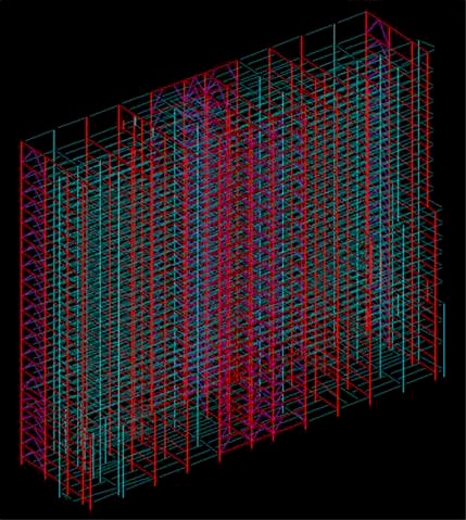 |
| RAM Frame Model of Combination Framing System |
d. Analysis: Comparison with Original Design
Once the final lateral system design was modeled and analyzed in RAM Frame, several checks were made in order to determine the performance of the system and compare it with the original.
- i. Check for Strength
Whether or not the building satisfies serviceability requirements, strength criteria must be satisfied to ensure the safety and integrity of a structure. In order to achieve this, the structural members were first designed for gravity in RAM Beam and RAM Column. These results were imported into RAM Frame and analyzed using Drift mode and checking per LRFD standards. Each failing member was individually optimized until the building no longer failed due to inadequate strength. Where slenderness was a problem in several columns in the lower levels of the building (where story heights are larger and loading conditions are more demanding), bracing and stiffeners were modeled in the form of intermediate beams at half the storey height of the failing column. In the case that bracing would be preferable to stiffeners, these 'beams' were omitted where vehicular traffic would be obstructed by them. Only in these cases do the columns reach sizes of greater than W14x398.
ii. Check for Deflection
Once it was determined that no members in the design would fail due to strength criteria, drift was checked and found to be a concern. In order to reduce the drift of the structure to within H/400, or 8.14" in this case, moment frame member weights were iteratively increased until this criteria was satisfied. The sizes of structural members that were not rigidly connected to columns (as they are in the four rigid moment frames) were not increased, as their connections were assumed to be pinned and thus could not physically affect the lateral drift of the building. The depth of the girders was limited to W24 so as not to increase plenum depth beyond that of the original design. Once the girders in the moment frames reached W24x146 in the E-W direction, a drift of 8.09" was achieved, and the design was considered optimized. This is by no means an unwieldy shape, and is acceptable by weight and depth standards for my purposes. Actual member sizes used would, of course, depend on fabricator availability at the time of construction to maximize economic efficiency.
| Total Drift | Drift Index | |
| East-West Direction | 8.09" | 0.00248 |
| North-South Direction | 7.99" | 0.00245 |
| Allowable | 8.14" | 0.00250 |
Displacement models (deflection x100) generated using RAM Frame are shown below.
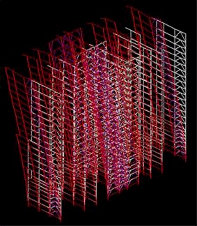 |
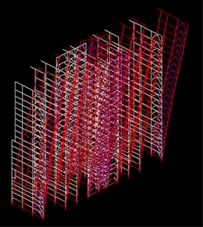 |
| Deflection x100 in E-W Direction | Deflection x100 in N-S Direction |
Several factors that can demonstrate the improvements made on the design of a building include a general member size comparison and cost analysis.
Due to the differences in building size and material, the total weight of steel used in each respective design will not give a meaningful comparison of the amount of steel material saved by redesign. Rather, a takeoff of steel beams on a typical floor was performed (columns were ignored because column size was not drastically altered). On a typical office level floor (level 6) the takeoff results are as follows:
| Total Weight of Steel Beams per Floor | Takeoff Method | |
| Original | 198,021# | Structural Plan Analysis |
| Redesign | 96,728# | RAM Frame Takeoff Report |
The difference in results is obvious. Although the takeoff methods differed, the reduction in cost of steel in the redesign is drastic enough to conclude that reduction in weight will significantly affect both cost and structure.
1a. Cost Analysis
An approximate cost analysis of the structural system was performed per AISC estimation methods and RS Means Building Construction Cost Data 1999. The method used is a cost-per-square-foot analysis based on professional experience (this experiential information was gathered from both professors and AISC reports), assuming that it takes 1000 tons of steel to frame a 200,000 square foot office building. The redesign of 750 East Pratt represents a typical office building with few outstanding qualities other than the curved eastern façade, so this assumption is assumed to be fairly accurate. Quantity takeoffs for linear feet of steel per floor were taken using values from the RAM Frame Takeoff Report. Material costs only were considered for comparison purposes.
I have included a breakdown of my estimation methods for the redesigned structural system.
- A typical floor in the 750 East Pratt redesign is approximately 28,000 sf. Including the interstitial and penthouse levels, there are 20 levels of structural steel framing. This corresponds to a total square footage of 560,000 sf. (versus the original 360,000+ sf. of steel framing), or according to the above estimation, 2800 tons of steel. (The original building also included concrete as well as steel framing on the original three floors and roof of the substation.)
- Typical composite decking consists of 2", 20-gage deck. For a building this size, at least 500 squares of decking will be used, so the material cost per square foot is $0.81. RS Means 053 10 42700
- There are 6 fixed moment connections per moment frame and 4 moment frames per floor (plus 3 intermediate bracing 'floors') which corresponds to 552 moment connections in the redesigned structure.
- There is approximately 1200 linear feet of steel framing per floor which corresponds to about 95,000 square feet of steel to be fireproofed. Spray-on fireproofing costs $0.42/sf. RS Means 072 554 0400
- There are 826 lf of HSS bracing per E-W brace and 2067 lf per N-S brace. 5x5x0.25 tubes weigh 15.62 #/ft; 6x6x0.25 tubes weigh 19 #/ft and are the cutoff between 15-20 #/ft @0.72/ft and >20 #/ft @ 0.66/ft. There are no tubes smaller than 5x5x0.25 in the bracing system of the building. RS Means 051 110 0400/0600
- The area of the original concrete-framed floor plan is 22,600 sf. (67,800 square yards) per floor, and the poured-in-place slab is 6" thick. Normal weight concrete is $126/cy including forms and reinforcing steel. RS Means 033 130 1950
| Material | Cost per Unit | Quantity | Cost | ||
| Original | Redesign | Original | Redesign | ||
| Steel Framing | $500 per ton | 2000 tons | 2800 tons | $1 MIL | $1.4 MIL |
| Metal Decking | $0.81 per square foot | 360,000 square feet | 560,000 square feet | $291,600 | $453,600 |
| Moment Connections | Addt'l $50 per connection | 1020 moment connections | 522 moment connections | $51,000 | $26,100 |
| HSS Braces | ~$0.70 per linear foot | 1285 linear feet | 9090 linear feet | $900 | $6,400 |
| Fireproofing | $0.42 per square foot | 68,000 square feet | 95,000 square feet | $28,500 | $39,900 |
| Concrete Slab &Reinforcement | $126 per cubic yard | 101,700 cubic yards | 0 cubic yards | $1.28 MIL | $0 |
|
Total Cost... |
$2.65 MIL | $1.93 MIL | |||
The final materials cost of the structural system in 750 East Pratt is $1.93 million versus $2.65 million originally (a materials cost analysis was performed on the original design using the same methods). Based on this preliminary comparison, it is easy to see that the unified structural steel design saved materials cost significantly over the original combined design. Considering that concrete also procures a higher labor cost due to formwork and curing, I conclude that, economically, a building framed entirely in steel (and favoring braced frames over moment frames) is preferable to the existing dual material design.
Note - Not including the first three floors and the interstitial level, the total area (of the office tower portion of the building) is now 448,000 sf as compared with the original 360,000 sf. The first three floors of the building were not originally framed entirely in steel.
1b. HVAC Considerations
The added volume of the 750 East Pratt redesign necessitates a check as to whether the mechanical equipment needed to service this volume can be easily added to the existing. Extra cooling towers and chillers will be located on the roof adjacent to the mechanical penthouse with the existing equipment. The area of the mechanical penthouse level is increased by 140% in my redesign, while the overall floor area of the building is increased by 156%. There exist on the roof three cooling towers for immediate purposes. Two future cooling towers will accommodate two future chillers for BG&E expansion, and space for these was accounted for in the original design. The 140% increase in roof area will easily accommodate the additional towers required for the increased office level volume. The mechanical penthouse will be expanded 30' to accommodate additional equipment needed. No specific calculations were performed to verify this.
2. Architectural Considerations
a. Interior Architecture
To fully take advantage of the newly optimized structural system, several aspects of the building architecture were necessarily revamped. One most obvious effect of the structural optimization was the alteration of the column grid. In addition to a more even distribution of forces, the new symmetrical grid corrects the irregular placement of interior columns. Irregular column spacing is more obvious to the occupant in such a large open office plan as the one typical of 750 East Pratt, and correction of this would be a subtle improvement in the architectural environment.
With the alteration of the grid, staircases and elevator shafts were relocated in such a way that fire safety and egress requirements were satisfied, structural support of the shafts was maximized, and the layout of the overall plan was not significantly changed. For building use group B (business occupancy), the required length of exit access travel is 250 feet with a sprinkler system installed, and 200 feet without. BOCA 1996
The maximum distance to an egress stairwell from several possible locations in the open plan is well under the allowable 200 feet, which allows for the absence of a sprinkler system as well as increased requirements due to the height of the building.
The Level 4 sky lobby was originally designed to separate the electrical substation completely from that of the office and retail spaces above, and so the vertical transportation for the two differing usage areas of the building remained separated in my redesign as they were in the original. The Level 1 street lobby remains an intermediate thru-way between the street level and the main lobby on the 4th floor. Vertical transportation is conceptually the same as the existing, which is illustrated in the Architectural Existing Conditions section.
b. Exterior Architecture
The façade of 750 East Pratt required consideration due to the addition of eight stories of office levels on the north end of the building (made possible by the structural improvements). The goals of this design were, as previously stated, to preserve two concepts: 1. the integration between the low-rise industrial section and the high-rise commercial section of Baltimore, and 2. the integration between the rectangular grid of the city to the East and the curved river to the West.
 The first design goal was achieved by extending the concept of using differing cladding materials
to represent occupancy use. The heavy decorative masonry is reminiscent of the architecture of the 70s, when the substation was first built, and the architecture that is representative of much of the low-rise industrial section of Baltimore. In the revised version of the building, this masonry cladding indicates not only the location of the substation but the fact that it is integrated with its surroundings: the second level of masonry on the northern façade of the building connects it conceptually with the architecture of the parking garage across the street, to which it is also physically connected via a pedestrian bridge. This additional masonry cube also emphasizes the cut of the curved glass façade into the rectangular, grid-like reflection of industrial Baltimore. Masonry columns draw the eye toward the architectural wall and eyebrow at the top and help to extend this idea through the entirety of the building.
The first design goal was achieved by extending the concept of using differing cladding materials
to represent occupancy use. The heavy decorative masonry is reminiscent of the architecture of the 70s, when the substation was first built, and the architecture that is representative of much of the low-rise industrial section of Baltimore. In the revised version of the building, this masonry cladding indicates not only the location of the substation but the fact that it is integrated with its surroundings: the second level of masonry on the northern façade of the building connects it conceptually with the architecture of the parking garage across the street, to which it is also physically connected via a pedestrian bridge. This additional masonry cube also emphasizes the cut of the curved glass façade into the rectangular, grid-like reflection of industrial Baltimore. Masonry columns draw the eye toward the architectural wall and eyebrow at the top and help to extend this idea through the entirety of the building.
The second design goal is accomplished through contrasting the curvatures of the western façade with the sharp corners of the eastern façade. The reflective glass curtain wall reflects the water below literally while its curved shape reflects the form of the river flowing by. Details in the architecture supplement this theme. Like that in the original design, an architectural eyebrow follows the curve of the glass façade and accentuates the shape. The architectural wall above the eyebrow was altered to more closely follow the themes of the building: instead of the original sharp triangular shape, an inverted semicircle emphasizes the opposing curve of the eyebrow. The original aluminum cladding on the wall was changed to masonry to mimic the lower portion of the façade and draw the design together, as was mentioned previously.
Overall, the architecture of 750 East Pratt solves two major design problems: the concept of a "Gateway to the City" for incoming traffic on a major artery, and the creation of an inviting public space in the plaza separating the building from the adjacent river. This second design problem can be solved through the lighting design of the space, which will be addressed in the Lighting Considerations section.
3. Lighting Considerations
The lighting design of 750 East Pratt entailed that the decorative lighting of the architectural features on the roof of the building and a safe and comfortable illuminance level at the pedestrian walkway be combined into one integrated lighting theme.
Floodlighting is positioned at the base of each eyebrow supporting column as well as between each column. This creates the effect of washing each column with high levels of light and making them stand out prominently against the more softly lit architectural wall behind them and eyebrow above, while minimizing the number of fixtures necessary for the desired result.
According to the IESNA Handbook, parks, plazas, and pedestrian malls should have a horizontal illuminance of 5 footcandles, while walkways near roadways should have a horizontal illuminance of 10 footcandles in commercial areas. As 750 East Pratt is located at the hub of several major roadways, I designed the plaza for the higher illuminance level in the interest of pedestrian safety, even though it is not directly adjacent to a roadway. Critical design issues for this type of space include color rendering, glare, reflected glare, and shadows.
- i. Color Rendering
- Color rendering is highly dependant on the type of lamp used. Metal halide lamps were used in all luminaires at the pedestrian level. Almost all varieties of white-light metal halide lamps have good color rendering properties which are achieved by a phosphor coating. Warmer or cooler colors can be achieved depending on preference. Metal halide lamps have color rendering abilities superior to any other type of HID lamp. Because of these properties and the high efficacies (75 to 125 lumens/watt), metal halide lamps were chosen to light the walkway.
- ii. Glare/Reflected Glare
- The decorative luminaires selected for the walkway were altered using 3D AutoCAD, resulting in matching wall-mounted fixtures. To reduce glare at the pedestrian level, these luminaires were placed at least 16' from ground level. While not overbearingly high, they no longer pose a direct glare problem. Reflected glare, on the other hand, is a positive effect where a metallic glass façade across from a river create specular reflections from the decorative luminaires.
- iii. Shadows
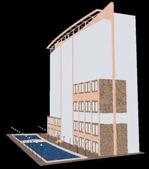
- Shadows are at a minimum. Light is distributed evenly over the ground level, as is demonstrated in the false color images below. The pedestrian bridge and centralized seating area have a slightly smaller illuminance, creating a more intimate atmosphere in these areas while retaining the required illuminance level. This effect is demonstrated by the rendering shown.
The shadows on the central portion of the façade also serve to accentuate the architectural illumination above the pedestrian area.
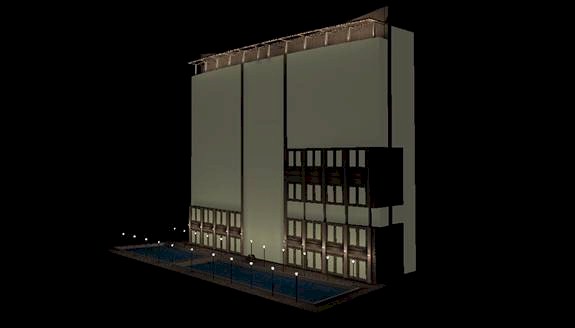 |
| Rendering |
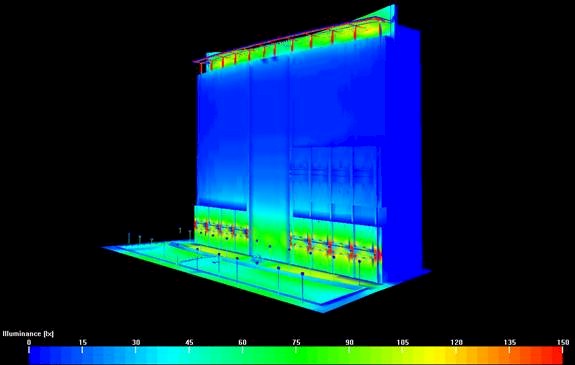 |
| False Color Image |
The pole fixtures at the pedestrian level are Bega 8135MH pole fixtures placed at 30' except at the center, where a slightly lower illuminance is desired. They are lamped with 70 watt metal halide bulbs with a luminous flux of 5000 lumens. The wall mounted fixtures are custom fixtures created to mimic the Bega pole fixtures, and are lamped likewise. They are positioned symmetrically at the column lines of the building, and the pole fixtures line the edge of the river to cast specular reflections on the water as well as effectively light the pedestrian traffic areas. An illuminance of 10 footcandles (100 lux) is achieved on the walkway with the exception of the aforementioned shadowed areas.
The floodlights at the roof level are lamped with 175 watt metal halide bulbs with a luminous flux of 14000 lumens. This high intensity accounts for the harsh wash desired on the columns as compared with the other architectural features as well as the large light loss factor associated with an exterior lamp with such an inconvenient location for maintenance.
All of the lamps involved in the exterior illumination of 750 East Pratt are metal halide bulbs. This provides more convenient maintenance and the opportunity to buy in bulk, both of which reduce the long term cost of the system.
The IESNA/ASHRAE 90.1 table 9.3.2 states that the power limit for a building façade is 0.25 watts per square foot of illuminated façade area. Power usage of the lamps is tabulated as follows (based on a front façade square footage of 87250 sf):
| Lamp | Quantity | Unit Wattage | Total Wattage | ...per square foot | |
| Bega 8135MH | Pole Mount | 22 | 70 W | 1540 W | |
| Wall Mount | 10 | 70 W | 700 W | ||
| Flood | 22 | 175 W | 3850 W | ||
| Total Wattage: | 6090 W | 0.0698 W/sf | |||
The power density of 0.0698 watts per square foot is drastically less than the allowable 0.25 watts per square foot of surface area. This allows for extra decorative, entrance, and emergency lighting as necessary.
See Appendix F for details on lamps and luminaires used in this lighting design.
Table of Contents