750 East Pratt Office Tower is located on Pratt and President Streets in downtown Baltimore, Maryland. Construction began on May 2, 2001 and completion is expected in November 2002. The 15-story tower is being constructed as an addition to an existing 3-story electrical substation owned by Baltimore Gas & Electric (BG&E). Originally conceived of in the 1970s, unexpected declines in economy and commercial demand in the city delayed its construction until the present. The original architect of the building was RTKL Associates, and the firm had the opportunity to be involved in the eventual culmination of the project. RTKL Associates is performing the architectural, structural, and MEP design for 750 East Pratt. The Whiting-Turner Contracting Company is responsible for the construction of the building.
The location of 750 East Pratt created a unique architectural opportunity. The building serves as a transition between the nearby low-rise industrial buildings and the more commercial downtown core of Baltimore. Additionally, the site is bordered by a traditional city grid to the West and the curved line of Jones Falls to the East. Interstate 83, a major vehicular artery into Baltimore, is to the North of the site, and the Inner Harbor is to the South. The western side of the building is a rectangular glass block, mimicking the grid of the city, while the eastern side is a soft curve of glass which responds to the curving river below. An aluminum architectural wall serves as the division between these contrasting themes.
In addition, 750 East Pratt is the first in a series of buildings designed to revamp the look of downtown Baltimore. The building is one of the first landmarks visible when entering the city via Route 83. It is an imposing twenty-story structure that meshes the 70s architecture reflective of the last construction boom in the downtown area with the modern style that represents how rapidly Baltimore is growing.
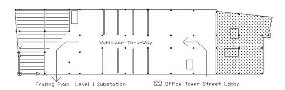
The plan of the building takes full advantage of the site. Approximate site dimensions are 350'x90'. The existing building reaches the edge of the site on the North, West, and East sides, but is between 60' and 76' from the Pratt Street border on the South side. The new addition reaches to the edge of the site on all four sides. BG&E requested that the substation remain independent from the addition in nearly all respects, so the ground level entrance to the office tower is adjacent to Pratt Street, and there is no public access to the building from the substation. The street entrance leads to a retail area and a secondary lobby. The main lobby (sky lobby) is on the 4th floor, and is the first level that is completely independent of the substation. This level can also be accessed via a pedestrian bridge which spans Lombard Street on the North and leads to a parking garage across the street. The 4th floor includes the sky lobby as well as retail space. Six elevators and one freight elevator service the 15 floors of office space from the sky lobby.
The building core is at the center of the western face of the building. Excepting emergency egress, all elevators, stairwells, electrical, mechanical, and telecommunications functions for the associated level are located here. The typical office level is a bare customizable open office plan situated around this core.
An interstitial level separates the BG&E substation from the office tower above. This level allows space for mechanical equipment which services the substation and the office tower separately, and a ¼" thick steel plate at this level protects office equipment from any electromagnetic disturbance produced by the substation. This level offers the additional advantage of minimal disturbance to the general building functions of the substation during construction. This is critical to the function of this substation, which serves much of the city of Baltimore. The existing mechanical equipment will remain in service while renovations are performed.
 |
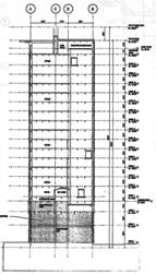 |
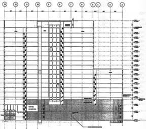
| Building Section: N-S | Building Section: E-W |
2. Structural Existing Conditions.
a. Foundation
The existing foundation employs belled caissons, and the new foundation as designed for the southern end of the building consists of both caissons and auger pressure grouted piles. The caissons bear on solid bedrock, allowing soil conditions for seismic calculations to be considered rigid. Piles extend to dense sand or disintegrated rock as required by the designer. Soil and site conditions due to the location of adjacent buildings and waterways drastically limit the choice of foundation systems for this building, and so foundation design was not altered in any way for the purposes of this thesis.
b. Existing Substation Superstructure
The existing electrical substation is composite steel and CIP concrete construction. Steel W-shape columns encased in concrete support a monolithic flat slab concrete floor system. A combination of concrete shear walls located in the center of the plan and steel braced frames at the exterior walls compose the lateral resisting system of the substation. These frames span from the east to west side of the building and form the majority of the lateral resistance that will be transferred from the above tower. Due to the unusually excessive and dynamic gravity loads imposed by the electrical equipment and vehicular pathway in the substation, the existing columns are likely massive enough to support the future lateral loading of the tower. Existing bays typically span 30'-0" in the longer direction, and 17'-0" at the plan center and 33'-6" at the northern and southern plan ends in the shorter direction. The narrower 17'-0" bay is a result of the required shear wall properties. Bays are a more "square" 32'-8" x 28-0" where the weight of the transformer and capacitor rooms must be supported and where columns do not have to be specifically located to accommodate the shear walls. Gravity loads induced by the heavier electrical equipment are accommodated by W-shape girders supporting the concrete slab. The composite system construction allows the addition of steel beams so that the thickness of the concrete slab can remain realistic.
|
c. Tower Addition Superstructure
d. Materials and Details
Superstructure Concrete Concrete Topping
4000 psi Columns and Column Encasements 6000 psi Reinforcing Steel ASTM A615 Grade 60 Welded Wire Fabric ASTM A185 -note: Lightweight Concrete Dry Weight: 107 pcf minimum - 116 pcf maximum Structural Steel Shapes ASTM A572 Grade 50 Steel Bars, Angles, Plates ASTM A36 Hollow Steel Shapes ASTM A500 Grade 36 -note: Bolts minimum ¾" dia. Composite Decking ASTM A653 Grade 33 ASTM A653 Grade 33 -note: Min. 2" Composite Floor Deck, 20 Gage;
1 ½" Roof Deck, Type B, 20 Gage Snow
Loading Ground
Snow Load
20 psf
Snow
Exposure Factor
0.7
Importance
Factor
1.0
Wind
Loading Basic
Wind Speed
70 mph
Exposure
Level
B
Importance
Factor
1.0
Seismic
Loading Effective
Peak Acceleration
<0.5
Seismic
Hazard Exposure Group
II
Site
Class 173,016’k 342.4
k
The superstructure for the office tower addition is structural steel members and composite steel deck floor system. Lateral forces are resisted by both moment and braced frames in the east-west direction, and moment frames alone in the north-south direction. The braced frames are located at the core of the building where they will not obstruct the open office plan and consist of chevron and V-braces to alternately resist wind and seismic loads. The moment frames in the north-south direction run along the glass curtain wall both at the rectangular West and the curved East façade. The composite decking floor system acts as a diaphragm and distributes the forces evenly to the lateral frames.
The structure of the office tower addition is largely governed by that of the existing substation. Column location is predetermined. The tower envisioned for the current project is larger than the one originally planned, and so connections between the existing and newly constructed structural systems had to be carefully designed to handle large transfer loads. As a result, lateral members are larger than they normally would be in such a structure, and moments transferred to the lateral columns are also very large.
Columns in 750 East Pratt are W14s. Typical gravity girders are W24s in the exterior bays, and W16s in the interior 17'-0" bays. The largest members are transfer and moment beams, which are typically W36s. Braces consist of hollow steel shapes ranging in size from TS10x10x0.625 to TS6x6x0.25.
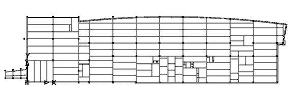
Typical Office Tower
Framing Plan: Level 6
e. Applicable Codes and Conditions
D
f. Structural Integrity Checks
Both gravity and lateral systems were checked using a combination of hand calculations and computer models. Although the original design used the ASD method, loads were checked using the LRFD method as I intended to use LRFD for the remainder of my analysis. Preliminary models were compared using both ASD and LRFD, and member sizes obtained using the LRFD method were generally slightly smaller than those obtained using the ASD method. The differences were not drastic.
Wind loads for 750 East Pratt were calculated using ASCE 7-98 standards and the conditions described above, in 'Applicable Codes and Conditions'. The building was found to be flexible in both the x- and y-directions
Seismic loads for 750 East Pratt were calculated using ASCE 7-98 standards and the conditions described above. Although the building is slightly taller than the 240'-0" height limitation required for the use of the Equivalent Lateral Force Procedure, this procedure was used for the sake of simplicity.
The results of these analyses suggested that deflection rather than strength controlled the lateral design of 750 East Pratt. Also, wind loads controlled the design of the East-West direction and seismic loads controlled the design of the North-South direction of the lateral system.
Shear at Base
Overturning Moment
Wind Load Results
E-W Direction
1056.4
k
833,934’k
N-S Direction
214.9 k
Seismic Load Results
E-W Direction
377.9 k
99,007.9’k
N-S Direction
68,394.2’k
The calculation spreadsheets used in this analysis can be found in Appendix A.
Table of Contents