![]()
Temel donanım bilgileri
© Copyright Brian Brown, 1992-2001. All rights reserved.
![]()
![]()
NETWORKS
The objective of this section is to
At the end of this section, you should be able to
![]() Network Topology's
Network Topology's
A network topology describes the configuration of a network (how
the network components are connected together). There are FOUR
main topology's.
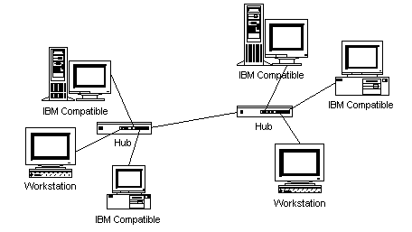
Fig 8.1: Star Topology
A star network uses a significant amount of cable (each terminal is wired back to the central hub, even if two terminals are side by side several hundred meters away from the host). All routing decisions are made by the central hub, and all other workstations can be simple.
An advantage of the star topology is failure in one of the terminals does not affect any other terminal, how-ever, failure of the central hub affects all terminals.
This type of topology is frequently used to connect terminals to a large time-sharing host computer.
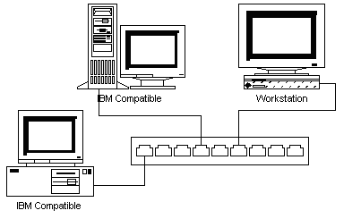
Fig 8.2: Ring Topology
Faulty workstations can be isolated from the ring. When the workstation is powered on, it connects itself into the ring. When power is off, it disconnects itself from the ring and allows the information to bypass the workstation.
Information travels around the ring from one workstation to the next. Each packet of data sent on the ring is prefixed by the address of the station to which it is being sent to. When a packet of data arrives, the workstation checks to see if the packet address is the same as its own. If it is, it grabs the data in the packet. If the packet does not belong to it, it sends the packet to the next workstation in the ring.
Ring systems use 4 pair cables (separate send/receive). The common implementation of this topology is token ring. A break in the ring causes the entire network to fail. Individual workstations can be isolated from the ring.
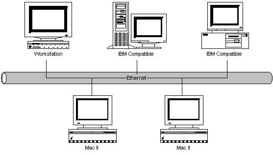
Fig 8.3: Bus Topology
If one workstation goes faulty, all workstations are affected. Workstations share the same cable for the sending and receiving of information. The cabling costs of bus systems is the least of all the different topology's. Each end of the cable is terminated using a special terminator.
The common implementation of this topology is Ethernet. A message transmitted by one workstation is heard by all the other workstations.
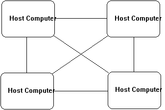
Fig 8.4: Mesh Topology
Mesh topology's are used in critical connection of host computers (typically telephone exchanges). Alternate paths allow each computer to balance the load to other computer systems in the network by using more than one of the connection paths available.
![]() Network Protocols
Network Protocols
This section describes the protocols used in different network
topology's. Remember that a protocol defines the rules for
sending data from one point to another.
In bus systems, all stations have access to the same cable medium. It is therefor possible that a station may already be transmitting when another station wants to transmit. Rule 1 is that a station must listen to determine if another station is transmitting before initiating a transmission. If the network is busy, then the station must back off and wait a random interval before trying again.
Rule 2 is that a station which is transmitting must monitor the network to see if another station has begun transmission. This is a collision, and if this occurs, both stations must back off and retry after a random time interval. As it takes a finite time for signals to travel down the cable, it is possible for more than one station to think that the network is free and both grab it at the same time.
CSMA/CD models what happens in the real world. People involved in group conversation tend to obey much the same behavior.
A station which wants to transmit waits for the token to arrive. When it arrives, it changes it from a token to a connector message, and appends its message on the end. This is then placed on the outgoing side of the ring.
Each station passes on received tokens if they have nothing to transmit. They monitor connector messages to see if the message is addressed to them. If connector messages are addressed to them, they copy the message, modify it to signify its receipt, then send it on around the ring. Connector messages which are not addressed to them are passed directly onto the next station in the ring.
When the connector message travels full circle and arrives at the original sending station, it checks the message to see if its been received. It then discards the message and replaces it with a token.
The master station sends a message to each slave station in turn. If the slave station has information to send, it passes it to the master station. The master station then sends the information to the desired slave station, or keeps it if the information is for itself.
Slave stations are very simple and have limited functionality. It is appropriate for industrial and process control situations.
![]() Network Facilities
Network Facilities
This section describe some common network facilities and
connections.
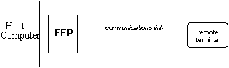
Fig 8.5: Point to point circuit
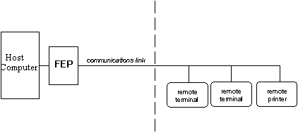
Fig 8.6: Multi-drop circuits
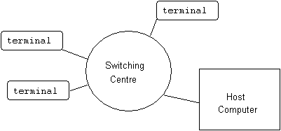
Fig 8.7: Switched Circuits
Each packet is transmitted through the network (and may take a different route from the previously sent packet), independent of other transmitted packets. They are reassembled at the destination end into the original message. The facility which converts a message into packets, and reassembles packets into messages is called a Packet Assembly/Disassembly (PAD) facility.
Charges are related to either time, the number of packets transmitted, or a combination of both. Distance charges are relatively non-existent.
Packet switching is very reliable, and public communications carriers offer packet switching as an alternative to other forms of connections (like leased lines for example). There is a high degree of error detection and control built into the packet switching protocol used to transfer packets from point to point in a network.
It offers the customer a single interface to support integrated voice and data traffic. Rather than using separate lines for voice (PABX system) and data (leased lines), ISDN uses a single digital line to accommodate these requirements.
The basic circuit provided in ISDN is the 2B+D circuit. This is two B channels (each of 64Kbits) and one D channel (of 16Kbits). The D channel is normally used for supervisory and signaling purposes, whilst the B circuits are used for voice and data.
A LAN is used to share resources amongst a group of individuals or company employees. These resources are typically
The characteristics of a WAN are
![]() LAN Connections
LAN Connections
A LAN connects resources together so they can be shared by users.
In today's terms, this often means linking PC's together. As
discussed earlier, the PC's can be linked together using a bus,
ring or star topology.
Each PC is equipped with a network interface card, which fits into an available expansion slot. Appropriate driver software provides an interface between the PC operating system and the network interface card.
Once the network software is loaded, access to provided to other machines on the network. There are THREE main types of network access provided.
Software programs are executed either locally, or on the peer computer. A user can take advantage of a faster computer by specifying that the program run on the faster machine, rather than their own.
The major problems associated with using Networks are
![]() Comparison of LAN and MAN
Characteristics
Comparison of LAN and MAN
Characteristics
| Characteristic | LAN | WAN |
| geographical size | 0-2Km | 1-100Km |
| number of nodes | 1-200 | 1-500 |
| data rate | 1-100Mbps | 1-100Mbps |
| error rate | <10-9 | <10-6 |
| delays | 1-100ms | 100ms-100s |
| routing | simple | sophisticated |
| linkage | bridges/repeaters | gateways/routers |
![]() Relationship between Network
Architectures
Relationship between Network
Architectures
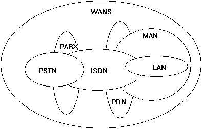
Fig 8.8: Network type comparisons
![]() Public Network Services
Public Network Services
Outline facilities available through public communications
services
	Students shall write a report of some of the following services

	videotext
	INFOS (statistics dept)
	NZBN
	OASIS
	Starnet
	Internet
	Compuserve
	Microsoft Network
![]() Summary
Summary
Network devices like computers can be connected in one of FOUR
topologies. A topology defines how they are connected together.
The four types are Ring, Star, Bus and Mesh.
Mesh topologies are used for networks which must be highly redundant and capable of withstanding failure. This is why telephone companies interconnect their telephone exchanges in a mesh type arrangement.
Bus networks use a common cable which is shared by all devices. A protocol called Carrier-Sense-Multiple-Access with Collision Detection is used to transmit data onto the common cable.
In token passing networks, a free or empty token is passed from each device to the next device on the ring. A device wanted to send data waits for the arrival of a free token then fills it with the data it wants to send.
In a polled network, a master device queries each other device in the network at regular intervals to see if that device has any data it wants to send.
A Local Area Network connects a number of computers and devices together in the same office or building. It allows users to share resources like files, data, and printers.
![]()
![]()
Home | Other Courses | Notes
| Tests | Videos
© Copyright Brian Brown, 1992-2001. All rights reserved.