Experimental
Mike Geusic, Michael Geusic, M. E. Geusic
II. EXPERIMENTAL
A. Introduction
Through the use of laser vaporization, clusters of a number of elements in the periodic table have been produced within the throat of a supersonic pulsed nozzle. An overview of events for a typical experiment is sketched below. Supplemental details for certain components18 follow in the later sections.
A typical experimental sequence begins with a pulsed double solenoid nozzle which is used to produce 200-400 us pulses of helium (FWHM). This helium pulse flows down a .2 cm diameter tube during which time it passes over a rotating sample target and at the maximum intensity of this pulse over the sample, a Q-switched Nd:YAG laser (second harmonic), focused to a .1 cm diameter spot upon the target rod, is fired. The laser pulse vaporizes the sample producing a plasma which is entrained within the helium carrier gas. An exit channel, .2 cm in diameter and of variable length, enables sufficient three-body collisions to produce clusters prior to expansion. The helium plus cluster beam then proceeds downstream where it is skimmed twice for collimation purposes and the beam then enters into a collisionless high vacuum ionization region of a time of flight mass spectrometer (TOFMS).
Once in this region a number of lasers may be used to investigate cluster distributions. Vibronic absorption spectra may also be taken using resonant two-photon ionization. Mass selective detection is accomplished with a time of flight mass spectrometer used to monitor the resulting signal. This signal is then multiplied and digitized using a fast 20 MHz transient digitizer. Once digitized, the signal is read through the Camac dataway to a lab minicomputer (MIK RT-ll/2) for processing. This final step allows for averaging and normalization of the incoming signal in order to correct for intensity fluctuation within the source.
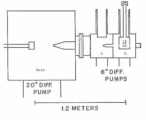
B. Vacuum System - AP2
A side view of the overall vacuum system as seen in Figure 2 consists of three chambers which are labeled "main, A, and B". The main chamber is a large stainless steel cylindrical can with a volume of approximately 600 liters and encircled by four flanges equally disposed about its diameter. The two side flanges are equipped with laser input windows, electrical feed-throughs, and gas-line inlets. A tri-directional translation stage is mounted upon the back flange supporting the nozzle and vaporization source and permitting alignment of the molecular beam.
Figure 2
The top of the main chamber is removable which makes sample changes or nozzle adjustments a simple procedure. Inside the chamber, a skimmer (Beam Dynamics .3 cm diameter, 30 degree conical angle) is mounted off the front wall and positioned approximately 35 cm downstream of the nozzle. A HS20 Varian diffusion pump (20 inch diameter, type 165) which is capable of pumping 21,000 liter/s of helium in the range of l.3 x lO-3 to l x lO-9 torr is backed by a Ruvac WA-series roots pump and provides adequate pumping. Under normal operating conditions, a base pressure of l x lO-4 and l x lO-6 torr is maintained with the molecular beam on and off, respectively. Separation of the main chamber from "A" and "B" is accomplished through the use of a four inch numatic gate valve.
The "A" chamber is a stainless steel cube but much smaller with a volume of approximately 30 liters. Side flanges are equipped with laser input windows and ionization gauges, while the top is fit with a liquid nitrogen cryotrap used for additional pumping of condensable gases. The "A" chamber is pumped by a VHS-6 Varian diffusion pump (6 inch diameter, type 184) with the capability of pumping 3,000 liters/s of helium in the range of l.5 x 10-3 to l x lO-9 torr, and backed by a Welch Duo Seal vacuum pump (model #1397). The base pressure of this chamber is l x lO-6 and l x lO-8 torr with the beam on and off, respectively. Another collimating skimmer (1.5 cm diameter, 30 degree conical angle) is mounted inside and situated approximately 65 cm downstream of the nozzle.
The final chamber is also constructed of a stainless steel cube (volume approximately 30 liters) with two side flanges equipped with laser input windows, electrical feed-throughs, and ionization gauge. The end wall has been fit with a 1 inch diameter laser input window, and the top with a liquid nitrogen cryotrap in which the drift tube of a time of flight is placed. This "B" chamber houses the acceleration and draw-out regions of the time of flight mass spectrometer. These units are enclosed within a copper shroud in contact with the liquid nitrogen dewar. The pumping system is identical to "A" with a slight variation in the base pressure being l x lO-7 to l x lO-8 torr with the beam on and off, respectively.
C. Mass Spectrometer
The time of flight mass spectrometer used in these cluster studies (see Figure 3) is of the Wiley-McLaren19,20 design and consists of several basic components: a double stage acceleration region (labeled A-C), deflection plates, a drift tube, and an ion multiplier. A copper shroud encases the acceleration region connecting directly to the liquid nitrogen dewar in an effort to keep this area free from contamination (ex: backing streaming oil).
Ions are created in region A-B by way of photoionization using either an excimer or Nd:YAG laser system. These ions are then accelerated through region B-C to constant kinetic energy. And from here the ions pass through a field-free drift tube until they strike an ion multiplier (Johnson MM-l) for detection. A deflection area is contained within the drift tube so that a compensation of the initial beam velocities can be made helping to direct the ions onto the multiplier.
Acceleration of all singly charged ions to constant kinetic energy leads to the fact that their flight time will be proportional to the square root of the mass. This means that the ions separate into individual packets within the drift tube according to mass. Consequently, the lighter ion packets will strike the detector first and heavier packets will come later. This feature allows for a complete mass spectrum to be monitored in a single laser shot which enables the isotopes of a particular species to be detected simultaneously, but independent of each other.
In normal operation, the voltages listed below are applied to the corresponding components of the mass spectrometer:
repeller plate + 3,100 volts
draw-out grid + 2,660 volts
flight tube grid 0 volts
flight tube 0 volts
deflection plates + 0-500 volts
These voltages were determined using the equations outlined by Wiley-McLaren20 for maximum resolution.
All components of the mass spectrometer were constructed of either stainless steel or ceramic with two notable exceptions being the teflon insulation on the electrical lead wires and the copper shroud. The grids are 70 line per inch, 90 per cent transmission, stainless steel mesh (Buckbee Mears).
Figure 3
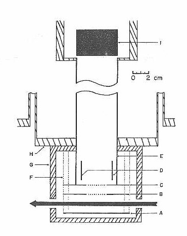
The spcings are: A-B = 2.54 cm B-C = 1.27 cm C-I = 112 cm
D. Nozzle
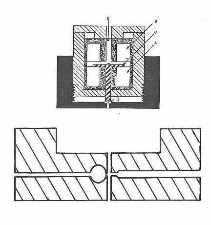
The pulsed nozzle used in these experiments is conceptually similar to the double solenoid design of Grant21,22 (see Figure 4 for side view). The valve is driven by two electromagnetic solenoid coils allowing for the nozzle to easily produce pulses of 200-400 us duration. The magnetic actuator (labeled C) consists of a disk (.3 mm thick, 12.8 mm diameter) and a plunger (2.5 mm diameter, .5 mm long) constructed from a single piece of ferromagnetic material for strength. The disk is placed between the pole faces of the coils which are separated by a 1.3 mm thick aluminum ring. The plunger extends through a bronze bearing fit within the center of the front (close) coil. The face of the plunger is what actually seals against an o-ring (Parker 0.002-2) on the face plate of the nozzle housing.
Figure 4
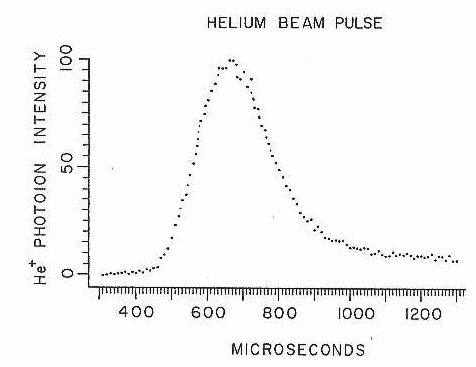
The nozzle control unit (see Figure 5) has been designed to allow for variable current pulses to be applied to both the front and back coils. The pulses are adjustable in length with the close coil being turned on as soon as the open coil is turned off. In normal operation the back coil is pulsed which causes the actuator to be pulled back off the sealing o-ring. The travel of the actuator (between 0.25-1 mm) is determined by an adjustable spacer or the tension of a small spring extending through the back coil as seen in the figure. A second pulse is then generated causing the close coil to turn on, pulling and holding the actuator back down onto the o-ring. The nozzle parameters (voltage, pulse length, spring tension, etc.) are adjusted such that a helium pulse of betwen 200-400 us (FWHM) duratlon (see Flgure 6) is produced, wlth a flow rate of approximately 1.5 torr liter at a backing pressure of 8 atmospheres.
Cooling of the nozzle housing is required since heating results from eddy currents that are produced within the coils and actuator. Both the coils and actuator are constructed of mild steel chosen for its high magnetic saturation property but whose low resistivity fosters the large production of eddy currents. The temperature problem is somewhat alleviated when we slot the coil housing, thereby causing a reduction in the eddy currents.
Figure 5
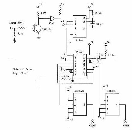
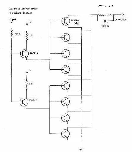
Figure 6
E. Laser Vaporization Source
The source is mounted on the front of the pulsed nozzle as shown in Figure 4. In this top view, two channels which lie orthogonal to each other within the same plane have been drilled. One is a .2 cm diameter channel along the molecular beam and the other is a .1cm channel which is used for the laser input. A third channel of. .25 inch diameter, which is mutually perpendicular to the other two, is drilled through the .1 cm channel directly after the point of bisection with the .2 cm channel.. The sample rod is inserted within this third channel forming a portion of the .2 cm channel wall.
Through the .1 cm channel, the second harmonic of a Nd:YAG laser is focused with a 1.0 m lense such that it is incident upon the target sample. The target rod is continuously rotated at a rate of .5 rpm on a micrometer screw with a 15 turn per cm pitch. If this rotation is not performed, then the reproducibility and the metal cluster signal is rather poor. These results are caused by the drilling of deep holes in the target which makes subsequent vaporization extremely difficult. This rotation rate produces a uniform vaporization area when irradiated at 10 Hz, with 10-70 mj's/pulse of the second harmonic of a Q-switched Nd:YAG.
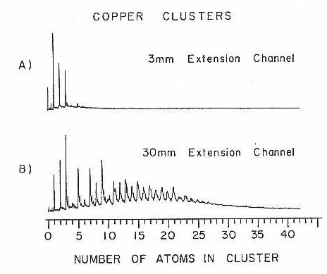
The cluster distribution which is achieved is governed by a number of parameters. The most important (with the exception of the third body: helium) is the length of the .2 cm channel from the point of vaporization to free expansion. This distance is critical in determining the maximum size cluster which is to be formed. Figure 7 illustrates a comparison between a .3 cm and 3.0 cm extension.These results are explained simply as permitting additional time for recombination to occur. There also has been observed a small effect on the cluster distribution which depends on the intensity of the vaporization laser and the time at which it is fired within the helium pulse.
Figure 7
F. Detection and Processing Scheme
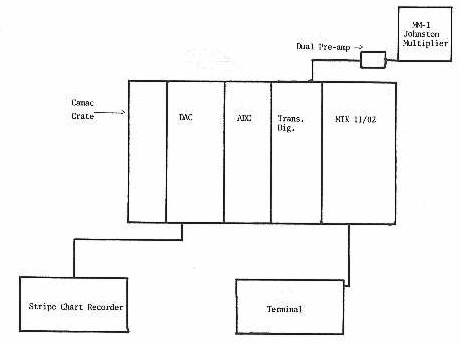
Once the ions have been created by way of photoionization, they are accelerated to constant kinetic energy and separated in time within the drift tube of the time of flight mass spectrometer. These ion packets then strike a Johnson multiplier (Model #MM-l) with a gain of up to 109 at 5000 volts. The analog signal is multiplied by an additional factor of l00 by two comlinear CLC-ll video amplifiers placed in series. From here the signal is digitized by a Camac-based fast Lecroy transient digitizer (Model # 2256AS), capable of sampling the analog waveform at a maximum rate of 50 nanosecond intervals. The digitizer then preforms an 8-bit analog to ditigal conversation storing the results in a 1024 word (16-bit) random accessible memory (RAM). The RAM is readout through the dataway into a lab minicomputer (MIK RT-ll/2) located within the Camac crate. At this point, the mass spectrum is processed so that it may be readout onto a terminal or written onto a floppy disk. From considering the digitizer's memory size it can be calculated that the maximum mass range in a single shot is 850 amu.
There are two other Camac-based modules besides the digitizer and computer. The first is a Bi-Ra (Model # 3101) 32 channel, l6-bit multiplexed analog to digital converter. This module enables the analog signals, such as etalon fringes or laser power measurements, to be monitored for each shot of the experiment, and allows this type of information to be processed along with the mass spectrum. The second module is a kinetic system (Model # 3112), 8 channel, 12-bit digital to analog converter. The second system allows the user to take any of the digitized signals discussed above and reconvert them to analog in order that they may be simultaneously plotted on a stripe chart recorder. In this particular case, the digital signals are read from the computer through the dataway to the converter in order that averaging of the signal can be done before plotting. Due to the computer's capability to handle and process incoming data, the detection scheme is run at a maximum of 10 Hz. Figure 8 presents a block diagram showing the overall detection and processing scheme.
Figure 8
G. Photoionization
The production of ions by way of photoionization23-26 has been shown to be an extremely gentle technique. The technique's major advantage is that under certain experimental conditions (low photon fluence) little or no fragmentation occurs. In cluster studies this turns out to be an important consideration because if fragmentation on a large scale has taken place, then interpretation of the data becomes extremely complex, if not impossible.
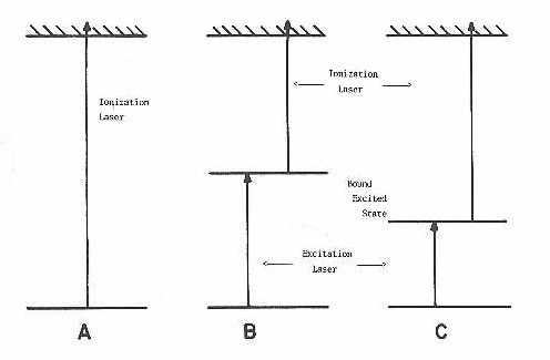
In this lab photoionization is accomplished using two basic schemes. These two types are presented in Figure 9 and can be seen to involve either a one or two-photon process. The first scheme involves a direct one-photon ionization of all species within the molecular beam. This process is mainly used for investigation of cluster distributions and relative intensities although, in order for intensity information to be useful one must assume similar absorption cross sections for all the species present. Normally with this scheme the F2 excimer laser (7.98 eV) line is used. The only major factor which must be considered with this type of ionization is the laser intensity. The photon flux must be kept low enough so that no multiphoton processess will occur.
The second scheme, a resonant two-photon ionization, is used in this lab mainly for the probing of bound excited electronic states of the species under study. This type of ionization can be accomplished through either a two-photon, one or two color scheme. In the two color process, two photons of different energies are involved. The first photon (excitation) is generated from a scanning Nd:YAG pumped dye laser. The second photon (ionization), chosen to be incapable of ionization, is supplied from a fixed frequency laser (either an excimer or Nd:YAG). The overall process is a resonant absorption of the excitation photon to a bound level of an excited state from where the ionization photon promotes the electron into the ionization continuium. In the two-photon, one color scheme, both photons are of the same energy and are supplied by the same laser. In this later case, it is understood that only bound states of equal to or greater than one-half the ionization energy, will result in ion production.
Figure 9
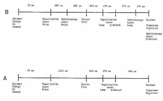
H. Timing Sequences
For the production and probing of these clusters, a sequential timing scheme is needed in order to control the precise firing of the independent components of the experiment. The timing sequence is initiated by a master oscillator which drives a series of Nimbin-based delay generators at a repetition rate of 10 Hz. Two schemes have been used for the experiments in this thesis and are shown in Figure 10 (labeled A and B). Timing scheme A is used to acquire simple mass spectrum; while scheme B is used for spectroscopic investigations via resonant two-photon ionization.
The master oscillator consists of a 3.5 MHz crystal oscillator divided down to 10 Hz. Also, within this unit is contained an Evans Associate delay generator which allows for an initial delay to be set with respect to time zero of the experiment. This then triggers a series of other delay generators, which in turn allows one to set delays between the various required events. These are all accurate to within + 1 ns. The master oscillator and delay generators (Evans Associate) are Nim-based and have been equipped with thumbwheel switches so the delays can be set accurately, in real time, without the need for an oscilloscope.
Figure 10