 |
|
|
|
|
|
|
|
|
|
|
|
|
|
|
|
|
|
|
|
|
|
|
|
|
|
|
|
|
|
|
|
|
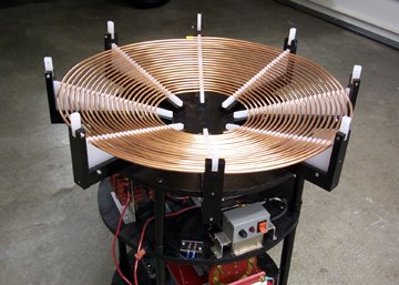
The Primary Coil |
|
|
|
 |
|
|
|
|
Specs:
Outside Diameter - 30" Inside Diameter - 9.625"
Primary to Secondary spacing - 1.5"
Wire - .25" copper tubing, 101' spaced .25" apart
No. of turns - 21
Angle from horizontal plane - 15 degrees
Total Inductance - 226.5uH |
|
|
|
|
|
|
 |
|
|
|
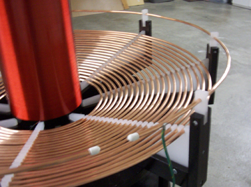
This is the primary coil design of my larger 6.5 inch coil. Because the secondary coil is larger and has more turns than the previous coil, the primary had to be larger in order to achieve resonance. |
|
|
|
 |
|
|
|
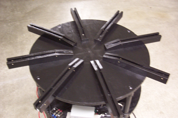
I grooved (8) 2 x 2 's with a rotary cutting tool as support bases and screwed them to the top deck using through-bolts. Notice the overhang - this primary is going to be big! |
|
|
|
|
|
 |
|
|
|
|
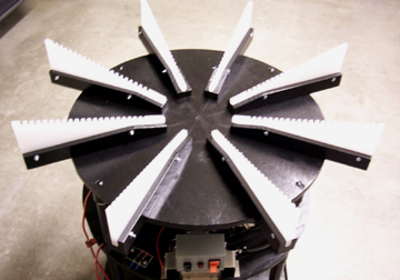
For supports I used poly cutting boards obtained from a department store. This material has good insulating qualities, but was not easy to cut. It melted using a radial arm saw and the only success I had was to use a sabre saw at an agonizingly slow speed. A band saw later proved to be a good tool for cutting this stuff. The grooves for the copper tubing were cut using a rotary cutting tool. A heat gun was helpful in melting down the burrs produced from cutting. Once cut and de-burred, they were secured in the grooved 2 x 2 support bases using screws through the base and supports. -------------> |
|
|
|
|
|
|
The winding of the primary coil went fairly easily, by pressing the copper tubing into the slots in the poly supports. Over 100 feet of tubing was needed to get the required 21 turns. It was not a continuous length;
I had to join 3 sections of tubing together by inserting a short length of #14 copper wire into the ends and soldering them in place to make one continuous tube. |
|
|
|
 |
|
|
|
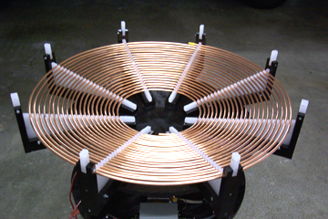
Short lengths of 1 x 2's slotted on one end were attached to each support base end. In the slots I secured a short piece of poly board with a 1/4" hole drilled through each one.
These are the supports for the strike rail. |
|
|
|
|
|
 |
|
|
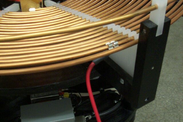
Fuse holders were used as the connection from the tank capactior to the primary coil. I soldered 2 clips to a small piece of printed circuit board. This easily allowed trying different tap points anywhere on the primary turns. |
|
|
|
|
|
|
 |
|
|
|
The strike rail was made from a single length of copper tubing fed through the small blocks of poly board, mounted about 2 " above the last turn of the primary coil and connected to earth ground. The purpose of the strike rail is to prevent arcs from the top of the secondary from hitting the primary coil, which in turn will blow out everything below it, including the neon transformers. This is an absolute must-have for a coil of this size and power. |
|
|
|