|
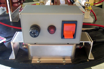
Power to the coil comes in through the 120 volt line cord which is connected directly to a 20 amp EMI line filter. The main purpose of this filter is to reduce interference the coil generates from getting back into the main power line and affecting other electronic equipment. The output of the EMI filter parallels the PFC caps and goes into the power control box. This box contains the main power switch, fuse, and indicator light, and is mounted on a bracket over the EMI filter to conserve space.
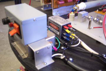
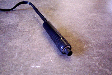
The output of the power control box supplies power to the rotary spark gap motor, and to a 120 volt DPDT relay via a handheld pushbutton switch. The purpose of the relay is for safety reasons. It isolates the high amperage draw of the Neon sign transformers from the pushbutton switch contacts.
The pushbutton switch controls only the relay, which draws only a small fraction of current. It in turn switches power to the NSTs. The relay contacts are rated at 20 amps each and are wired in parallel, making it effectively a 40 amp switch, more than enough to handle the load. |
|
|
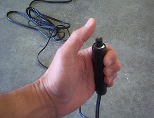
The advantage of the pushbutton switch is that the coil can be operated intermittently, and from a safe distance. Anyone who operates a Tesla coil in a continuous-on manner is asking for trouble; transformers, capacitors, spark gap, and filter components will be severely stressed and suffer early-life failures.
A coil should always be run in short bursts, or some kind of method giving intermittent duty cylces. |
|