 Mazda R100 type 1
Mazda RX, AP 1974 on, Electrical Information Section....
Pre 1974 there was very little in the way of electronics or electrical 'black boxes' on the car, but AP models from 1974 on had wiring looms to rival current day EFI vehicles, especially the Rx 4 and 5. This makes Electrical fault finding extremely difficult without the correct wiring diagrams and associated documentation. So we'll take a look through the wiring diagram and locate all the components, find out what each one does, and also how each one works internally.
Another problem for the would-be repairer is that the wiring diagrams are almost impossible to find... since I believe they only came in the original owners handbook, and not even in the genuine factory workshop manual. Some of the non-mazda publications do include the wiring diagrams but these books are equally as hard to find.
Frequently asked Questions:
Why does a buzzing sound come from under the dash when I put my foot on the brakes?
As standard.... all Rx 2,3, and 4 came fitted with a warning buzzer which can detect if a brake light globe is out and then will buzzzzzzz every time you apply the brakes until you replace the brake light globe. Rx5's did not come with this device, although the wiring plug is still present, but the two terminals have been bridged out with another mating plug. Easy to fix when you know whats going on!
My xxx is not working.... Where Do I start?
The first place to start if something is not working at all is of course the Fuse Box. Always check all the fuses before anything Else. Most of the time a visual inspection is adequate if you do not own a multimeter. Also keep in mind there are fusible links under the bonnet near the battery, and on the Rx5 there is also 2 on the back of the Ignition switch.
Wiring Diagrams:
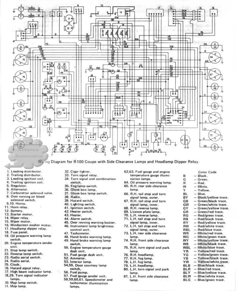
Mazda R100 type 1
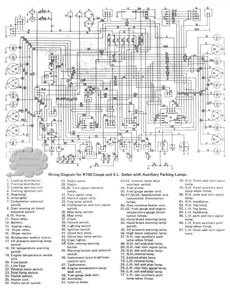 Mazda R100 type 2
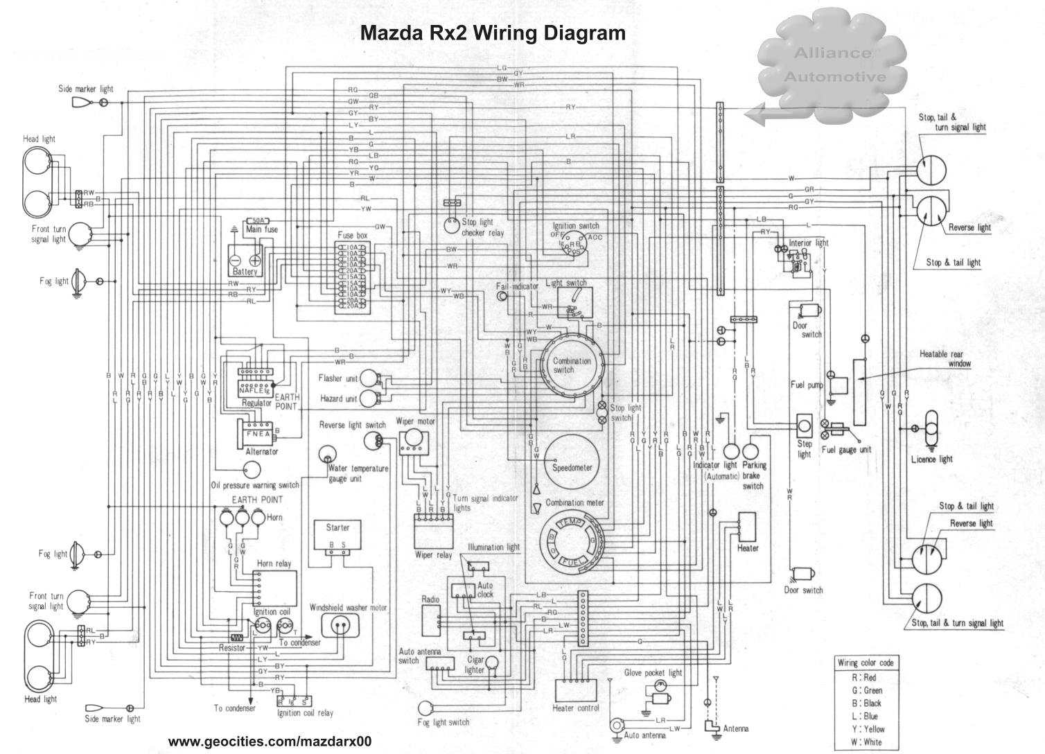 Mazda Rx2 Owners Manual Diagram
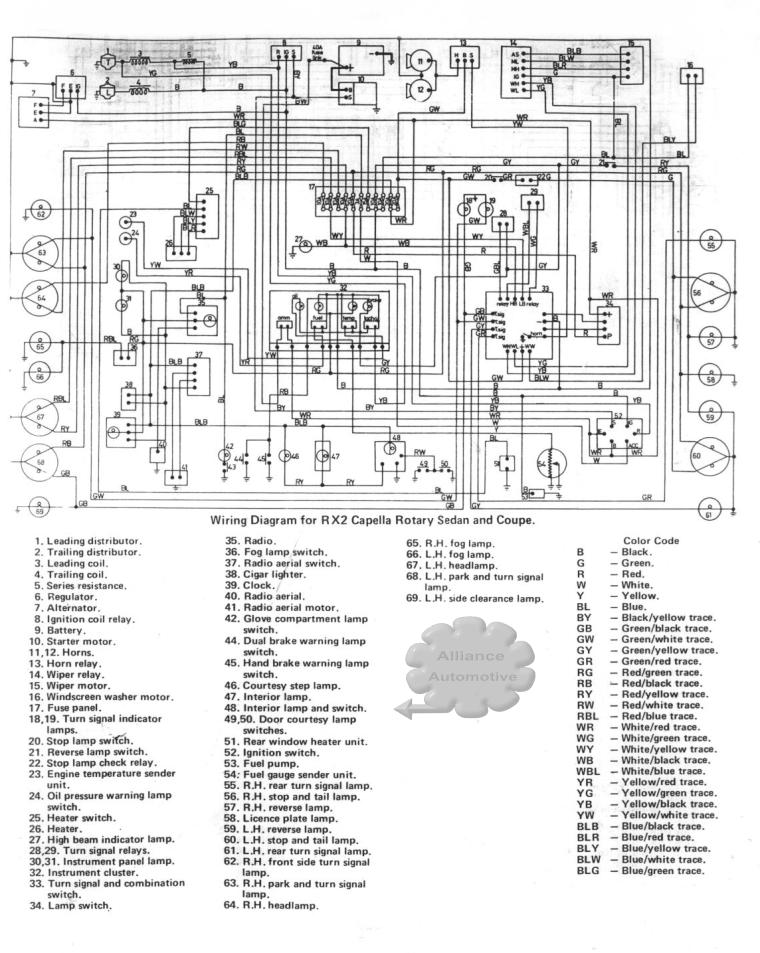 Mazda Rx2
Alternative
Mazda Rx2
Alternative
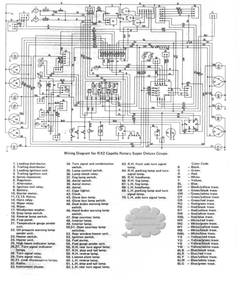 Mazda Rx2 Super
Deluxe
Mazda Rx2 Super
Deluxe
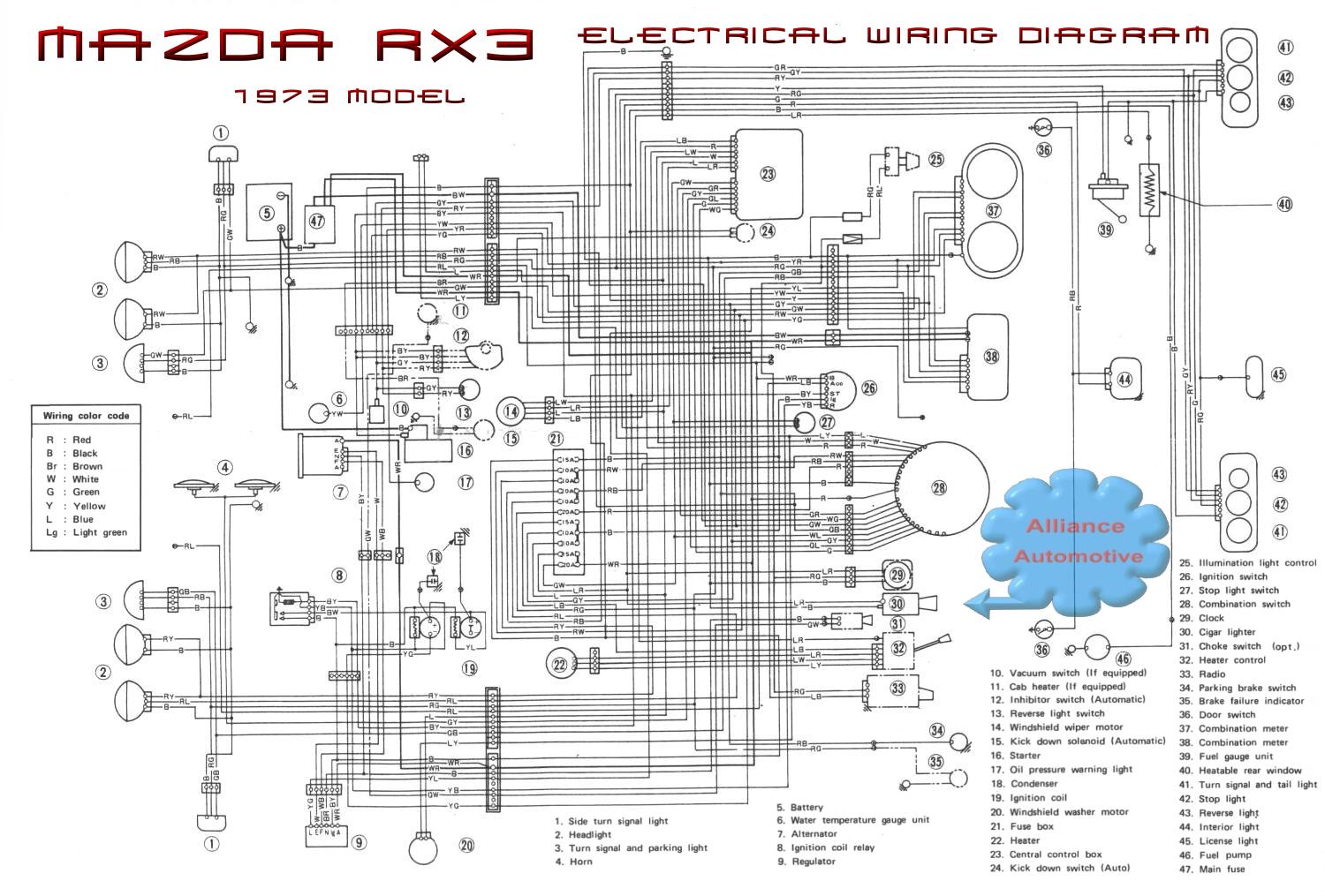
 Mazda Rx3 1974 AP on (also suit Rx2 AP ) ...
Emissions Control Wiring Diagram. This diagram shows all the extra wires in with
the normal wiring loom, which are used for emission control. Handy for finding
out what all those extra underbonnet wires used to be used for.... so they can
be safely removed, or used to power new devices...
Mazda Rx3 1974 AP on (also suit Rx2 AP ) ...
Emissions Control Wiring Diagram. This diagram shows all the extra wires in with
the normal wiring loom, which are used for emission control. Handy for finding
out what all those extra underbonnet wires used to be used for.... so they can
be safely removed, or used to power new devices...
 Mazda Rx3, factory wiring diagram.
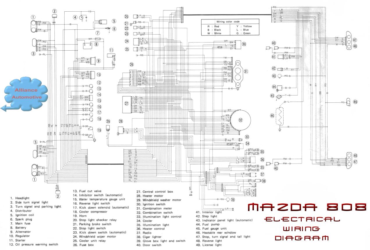 Mazda 808, factory wiring diagram.
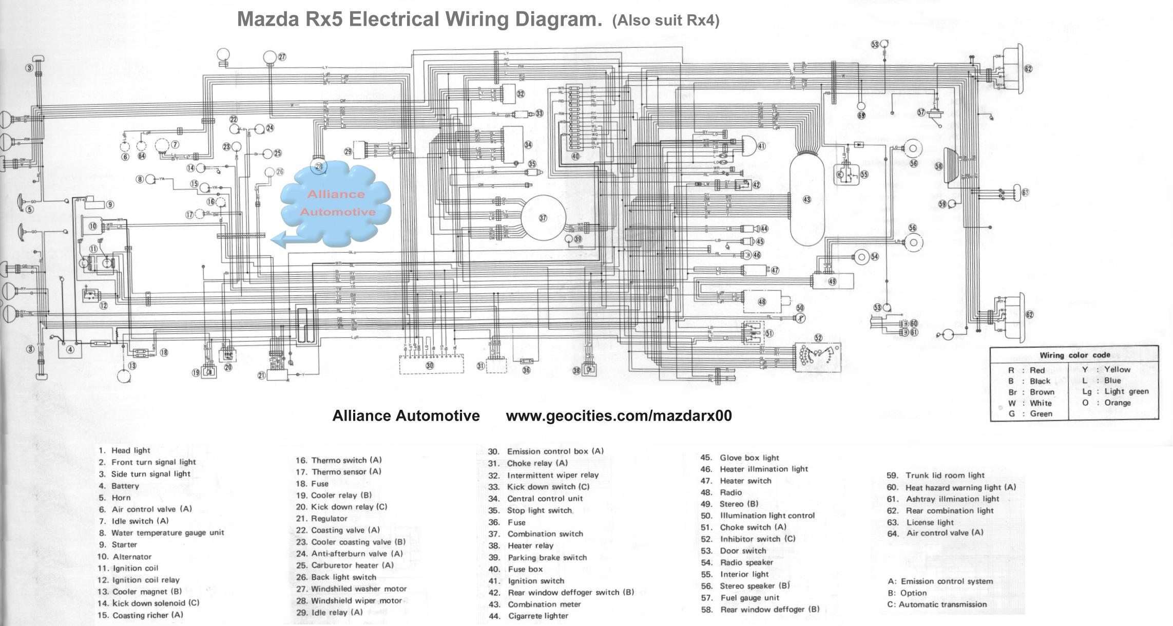 Mazda Rx5 (also suit Rx4)
 Mazda Rx5
Printable Version. Download all 4 parts and 'print to fit' each on an A4 Page!
 Mazda Rx5
Factory Wiring Diagram - Charging System / Starting System
Mazda Rx5
Factory Wiring Diagram - Charging System / Starting System
 Mazda Rx5
Factory Wiring Diagram - Meter and Warning System
Mazda Rx5
Factory Wiring Diagram - Meter and Warning System
 Page
1
Page
1
 Page 2
Mazda Rx5 Factory Wiring Diagram - Emission Control System, Kickdown (auto), Fuel Pump & Ignition System
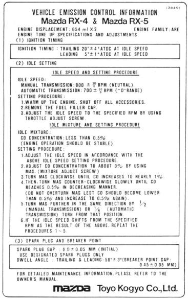 Tune Up
Information - Mazda Rx4/ Rx5 13B
Tune Up
Information - Mazda Rx4/ Rx5 13B
Mazda Wiring Color Codes
B - Black
R - Red
G - Green
L - Blue
Y - Yellow
Br - Brown
Lg - Light green (looks almost the same as white after 20 years)
O - Orange
W - White
e.g. LO is a Blue wire with an Orange stripe. LgR is a Light Green wire with a Red stripe.
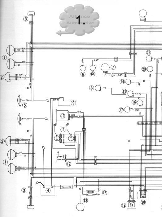
Mazda Rx5 Wiring Diagram Information:
In case you haven't already found out, sometimes even the Factory Mazda wiring diagrams aren't 100% correct, and do not go into detail about the actual items, such as the Instrument Cluster etc... Some items listed on the wiring diagram I have never found, but have found extra relays not listed at all. Also the Airconditioning wiring is very different from the wiring diagram..... and since I'm trying to fix my A/C system it makes life very difficult indeed.
1. Head Light
2. Front turn signal light (indicator)
3. Side turn signal light (indicator)
4. Battery
5. Horn
If you don't know where and what the top 5 items are.... then for #$#@ sake get someone else to fix your car :) please!
6. Air Control Valve
7. Idle switch
A Microswitch which is bolted to the front of the carby which makes when the throttle is fully closed. Pre Rx5 only.
8. Water Temperature gauge unit
Located on the left hand side of the rear Engine plate, next to the Oil Pressure Switch.
9. Starter Motor
10. Alternator
11. Ignition Coil
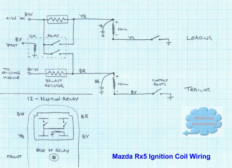
12. Ignition Coil Relay
NOTE: On 2 out of 3 cars this relay is not working and will need to be fixed if you intend on keeping the original Ignition System. Its function is to bridge out the Ballast Resistors during cranking (when the battery voltage is low) so as to give a better spark and therefore help the engine start easier.
The problem with these relays is that the ground for the relays coil is crimped under the case of the relay, and over time it gets corroded and no longer makes connection. The fix is to open up the relay, drill a small hole through the white plastic base, and solder a wire to the brass tab that connects to the case. Solder or Crimp a lug to the other end, and put it under the screw holding the relay in place.... easy.
13. Cooler Magnet (Optional Extra)
The actual clutch coil on the Aircon. Compressor. Rx5 only.
14. Kick down Solenoid (Automatic Transmission Only)
Solenoid on the Left hand side of the transmission with the one and only wire coming from the transmission.
15. Coasting Richer
16. Thermo switch
Located directly behind the Water Pump. Has two wires connected and goes Open when the Engine reaches operating temperature, to turn off the Automatic choke.
17. Thermo Sensor
On the Rx4 in the Centre Engine plate there was a large sensor that detected the temperature of the water gallery.
18. Fuse
19. Cooler Relay (Rx5 with A/C only)
The Cooler Relay is located right near the ignition coils on the LHS of the vehicle. Its function is to activate a solenoid when the vehicle is cruising and the A/C is on. If you have removed the pollution gear on your car then you may as well turf this relay as well. The A/C clutch is controlled from a different relay which is located either a:Under the bonnet on the LHS of the car behind the Strut Tower (for early models) or b:Above the LHS passenger footwell
**Also see 21. Regulator Circuit Diagram below for pinouts and further information on the Cooler Relay
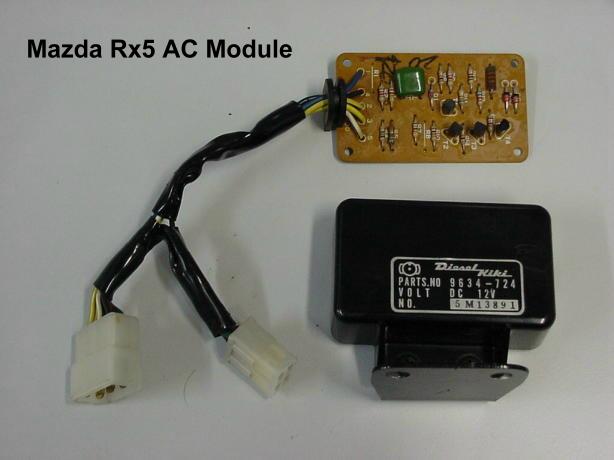
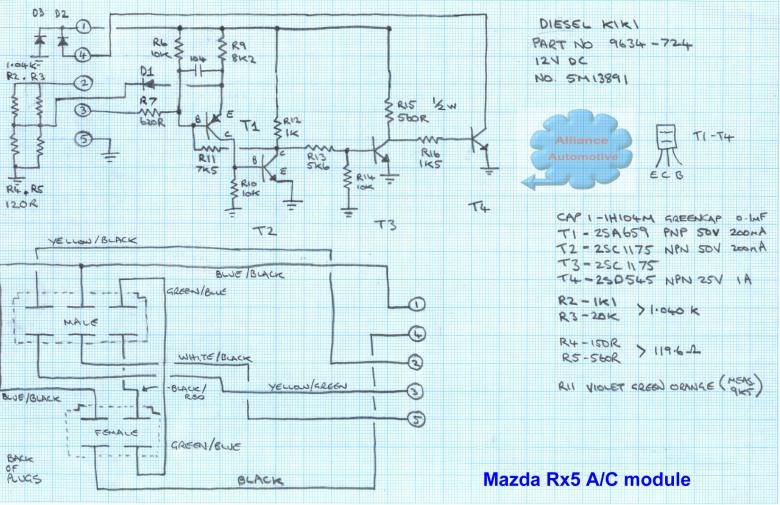 This module is not on the wiring
diagram!, but I believe its function is to control the
Temperature of the A/C.
This module is not on the wiring
diagram!, but I believe its function is to control the
Temperature of the A/C.
20. Kick Down Relay (Automatic Transmission Only)
Located under the bonnet behind the LHS headlights (in front of the battery). When the Accelerator pedal switch is made then this relay should come on, sending power the the Kick Down Solenoid on the Automatic Transmission. Also when the Choke is on (engine cold) the Kick down solenoid is energised to help warm up the Transmission.
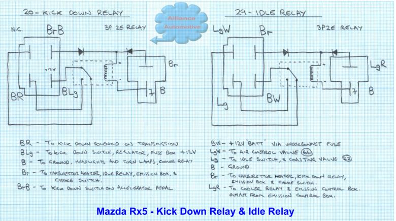 20. Kick Down Relay and 29. Idle Relay
wiring diagrams.
20. Kick Down Relay and 29. Idle Relay
wiring diagrams.
21. Regulator
Located under the bonnet, on the Left hand side, up the very top of the firewall.
An essential part of the Alternator (the regulator on all 1980- on alternators is internal to the alternator and not a seperate module as is the case on all the early Rx's). Its function is to regulate the voltage on the battery, when the vehicle is running to 13.8 volts (13.5 - 14.5v).
On one of my Rx5 the HEAT light was stuck on.... even after totally removing the Emissions module and the Heat Sensor!!!! the final fix was.... someone had installed an early model (maybe Rx2/ capella) Regulator in this car. These early regulators are missing the Extra brown wire with the spade lug on the end, consequently this wire turns on the choke relay when the engine starts, and turns off the HEAT lamp.... so after installing the correct Rx5 regulator.... no more HEAT lamp!!! wohoo.. at last I have found the root cause of the fault.
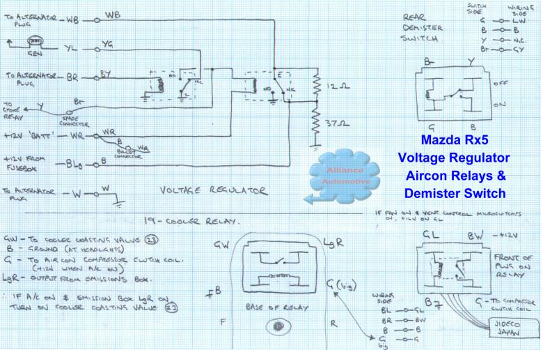 Regulator Wiring Diagram, Aircon Relays
and Rear Demister Switch.
Regulator Wiring Diagram, Aircon Relays
and Rear Demister Switch.
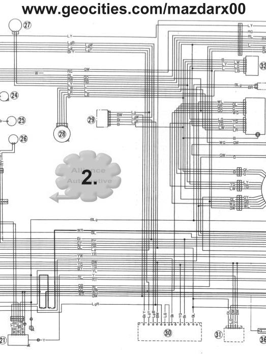
22. Coasting Valve
23. Cooler coasting valve (Optional Extra)
24. Anti afterburn valve
25. Carburettor heater
The Automatic choke heater coil on the carburettor. Closes the choke plate when cold then as the element heats up the bi-metallic spring opens the choke plate.
26. Back light Switch
Reversing switch, to bring on.... you guessed it.... Reversing lights!
27. Windshield washer motor
28. Windshield wiper motor
29. Idle Relay
Located under the bonnet behind the LHS headlights (in front of the battery). Controlled by the Emission Control Box. Switches on Air control valve (64) when not energised .... or Coasting Valve (22) when energised. If you have no Emissions computer or solenoids then get rid of this relay... it is doing nothing.
** see 20. Kick Down Relay for wiring diagrams of the Idle Relay.
30. Emission Control Box
On the Rx5 its above the passengers (LHS) footwell behind a metal cover, On Rx2 's its mounted on 4 studs, in the boot, on the metal panel behind the back seat behind the right hand side shocker mounting.
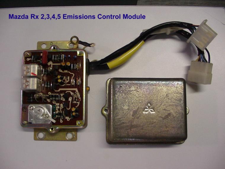
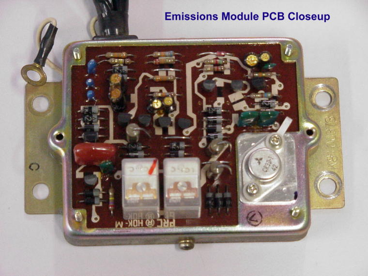 Check out these Electronics..... not bad
for 1974.. Those white lines are actually tracks on the top of
the board, and the black patches between the white squares...
resistors built in between them!!
Check out these Electronics..... not bad
for 1974.. Those white lines are actually tracks on the top of
the board, and the black patches between the white squares...
resistors built in between them!!
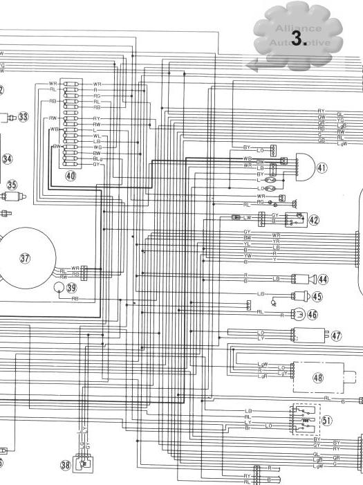
31. Choke Relay
Found above the left hand side passenger footwell, rectangular gold Relay. Controls the HEAT light on the Dash and also the coil to hold the Choke cable when you pull it out.
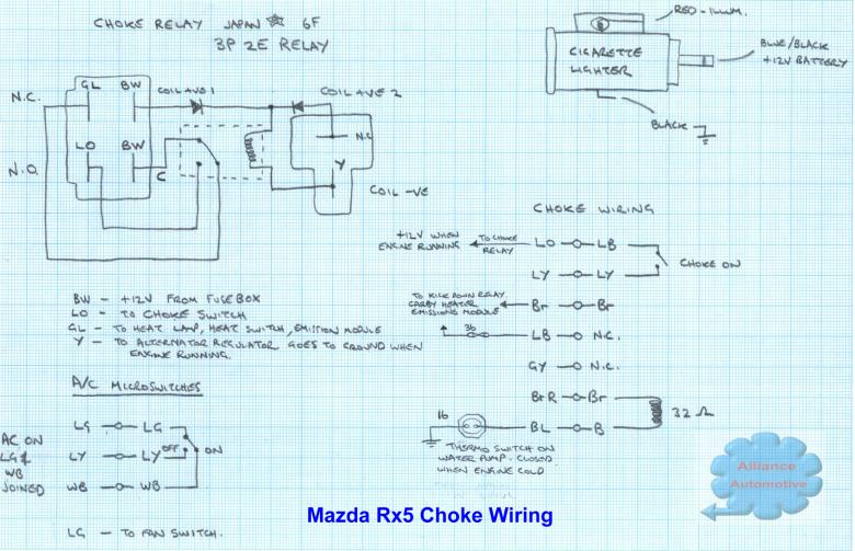 Choke Relay Pinout and also Electric
Choke Wiring.
Choke Relay Pinout and also Electric
Choke Wiring.
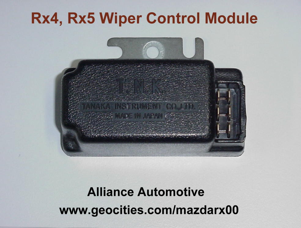
32. Intermittent Wiper Relay
Actually an Electronic module with a built in Relay, which lives up underneath the dash pad, in about the centre of the vehicle. Rx4 and 5 only.
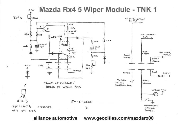 Circuit Diagram.
33. Kick Down Switch (Automatic Transmission Only)
The switch inside the cabin, underneath the accelerator pedal that makes when you 'floor it'
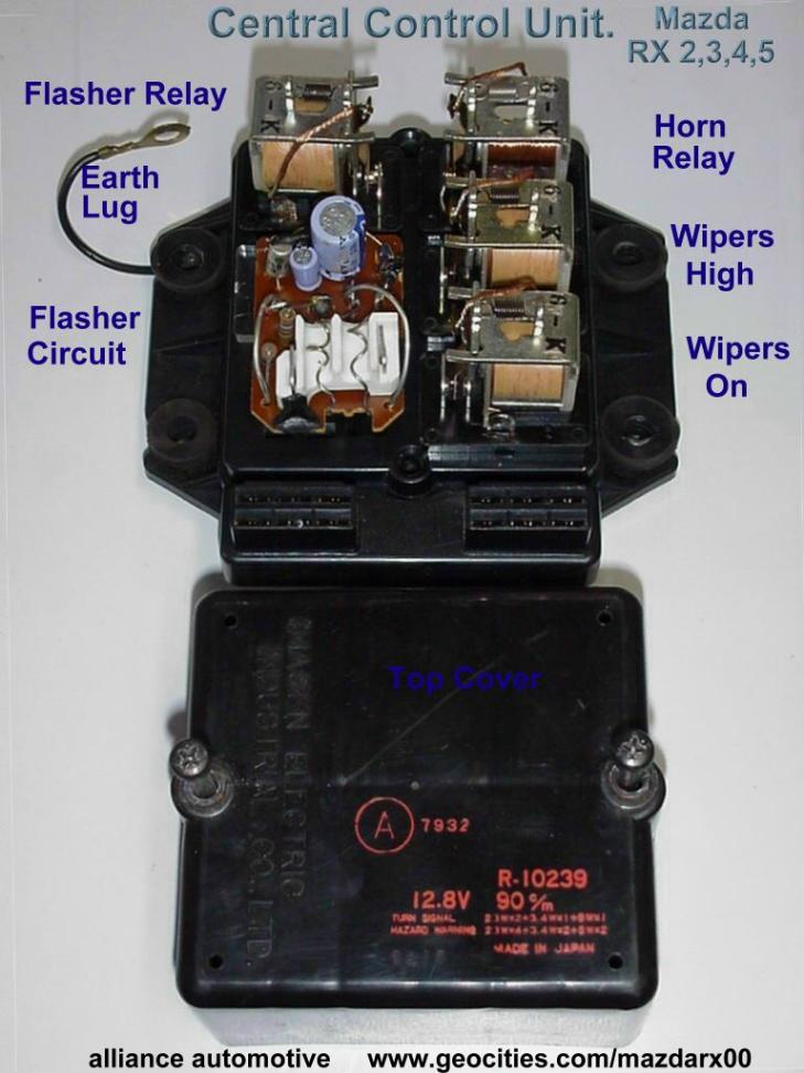
34. Central Control Unit
In the Rx2 it was on the far left side of the parcel shelf inside the car. On the Rx4 and 5 its up under the dash on the drivers, right hand side of the car. It takes care of the indicators, windscreen wipers (as well as 32.), and the horn.
 Circuit Diagram page 1
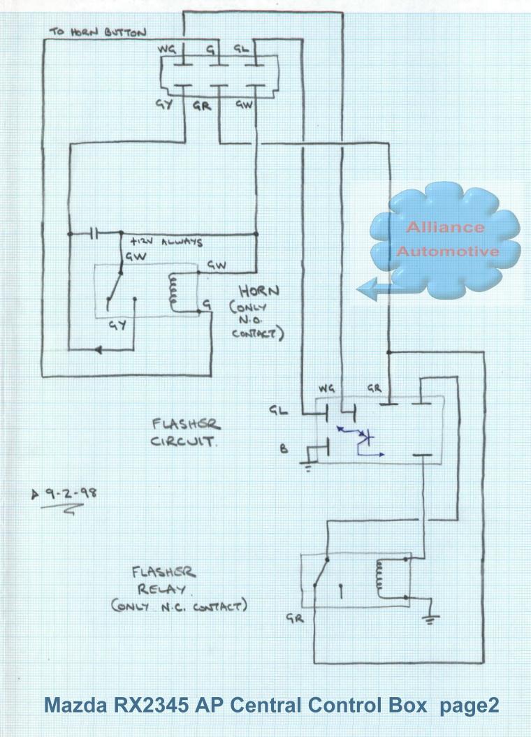 Circuit Diagram page 2
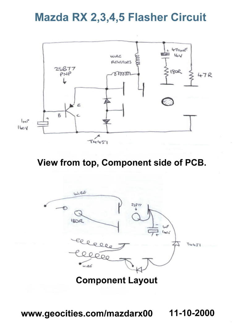 Flasher Circuit Diagram
35. Stop Light Switch
The Switch above the Brake pedal... comes on when you brake... surprise surprise :)
36. Fuse
37. Combination Switch
All the switches on the steering column, indicators, lights, wipers, washer.
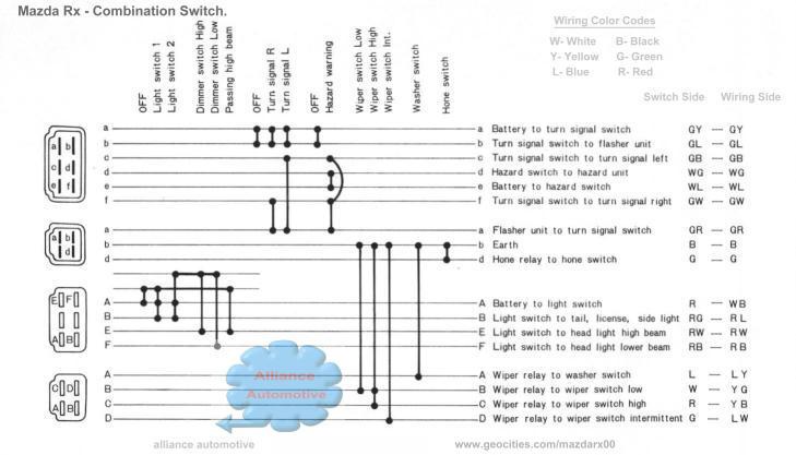 Combination Switch wiring diagram... a
MUST have... for all RX2345!
Combination Switch wiring diagram... a
MUST have... for all RX2345!
38. Heater Relay
39. Parking Brake Switch
The switch on the Hand Brake Lever.
40. Fuse Box
Where the fuses hang out :)
41. Ignition Switch
That's where your ignition key goes... duh
42. Rear window Defogger Switch (Optional Extra)
43. Combination Meter
Your Instrument Cluster as its also known.
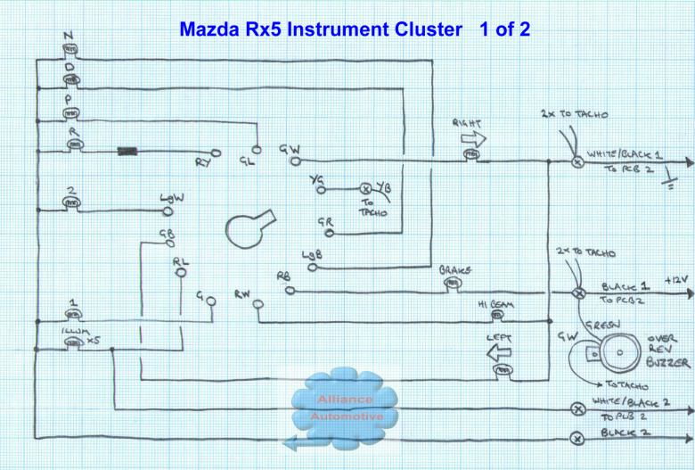 Speedo / Tacho side of the Cluster.
Warning buzzer shown is present on manual vehicles only.
Speedo / Tacho side of the Cluster.
Warning buzzer shown is present on manual vehicles only.
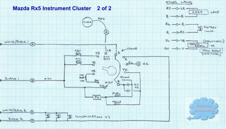 Fuel / Temp gauge side of the Cluster.
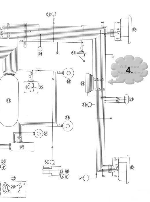
44. Cigarette Lighter
45. Glove box light
46. Heater Illumination light
47. Heater Switch
The fan speed selection switch.
48. Radio
Lovely AM... my fave!...................not :)
49. Stereo
Plays those old fashioned cassette thingies
50. Illumination light Control
The brightness control for the Instrument back-lights.
51. Choke Switch
A microswitch on the Choke lever that tells the emissions module whether the choke is on or not.
52. Inhibitor Switch (Automatic Transmission Only)
Stops you from starting the vehicle except in 'N' and 'P' positions. Located underneath the console on the Auto Lever.
53. Door Switch
For the interior light
54. Radio Speaker
The 12" subby thats mounted under the centre of the dash pad.
55. Interior Light
That's what makes it like daytime after you open the door !
56. Stereo Speaker (Optional Extra)
The two rear speakers
57. Fuel Gauge Unit
Fuel tank Sender
58. Rear window Defogger (Optional Extra)
59. Trunk lid room light
The boot light
60. Heat Hazard Warning light
The big red 'HEAT' light on the dash that comes on when you start turfing the emissions gear.... and still stays on even after removing the Emissions Control box..... damn :)
61. Ashtray Illumination light
62. Rear combination light
The Taillights
63. Licence light
Number Plate light
64. Air Control Valve
65. Heat Hazard Sensor
In the boot, under the Petrol tank on the Right hand side of the car. Normally Open Circuit, goes Short when the Floor Temp Exceeds 120 degrees C.
Rx5 Model Differences:
Since I have both an Early 1976 model and a Late 1977 model, I have noticed a few items which were updated between the models.
The 1976 model still has the large wiring connectors bolted to the firewall, so you can totally disconnect the engine bay wiring loom. The 1977 model does not, the wires are continous through the firewall which is most desirable. These connectors are a Major Source of trouble in the Rx3 and Rx4.
On the early model Instruments, the Temperature gauge when the ignition is off reads full scale Hot, same as the Rx2's I had. The Later model just has a normal temp gauge which starts at Cold. So really the early model gauges are better, as if the temp sender of wiring goes open circuit then the gauge goes to full scale HOT, so you know theres a problem in this very important gauge.
The Aircon module in the later model is adjustable externally with a pot (potentiometer) on the outside of the box, so you can adjust at what RPM the aircon will cut in at. I presume this is so the car will not overheat when idling and the A/C is left on.... as it is stated in the factory manual that the car is prone to overheating if left idling with the A/C on! On the Early model the A/C is on whenever the fan is on and the temp controls are set to the far two left most (cool) positions. I have added a switch to mine so I can have just the fan on without the A/C which is not possible with the factory system unless it is set to Heat.