return HOME return to Contraptions
This is some details about how I built a micro sized wind generator that charges Ni-cad batteries.
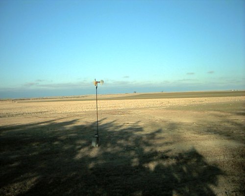
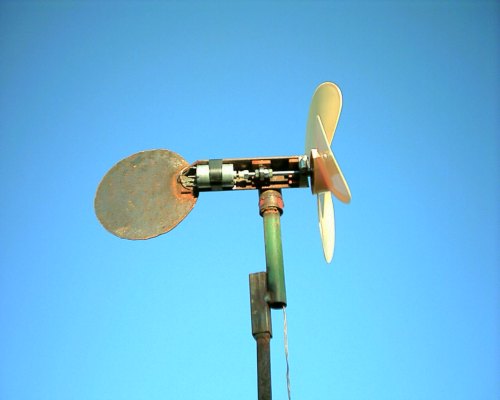
I was taking apart on old, dead, ink jet printer to salvage the useful parts, and saw the nice motor that runs the belt which runs the heads back and forth. (It's NOT a stepper motor) I hooked it to my volt meter, then gave it a spin by hand. Something like 6 volts! My immediate thought was something to help charge the solar lawn lights at my parent's house, since those things always seem to be off in the winter. So, I began dreaming of how to put it all together. It's shown here on it's "test" stand, but it was later put on the roof of my parent's house. And it needs a coat of paint!!
My first thought was make a PVC prop, put it on the shaft of the motor, and clamp it to a frame. I made the prop, put it on the motor, then went outside to test it. The prop didn't have enough torque to start it. If I spun it by hand, it would go. And it was a pretty windy day, too. This little motor has some serious cogging!
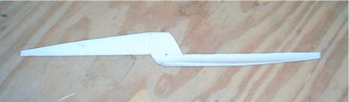
So, I tried a blade from a microwave fan. It spun, but not enough RPM's. Then I remembered I had an old desk fan blade laying around....that should work! But it was on an 8mm shaft, WAY bigger than the shaft of the motor......think think think.
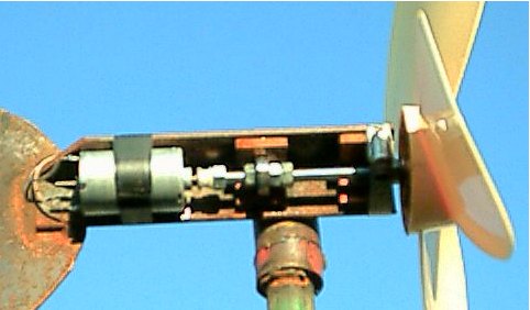
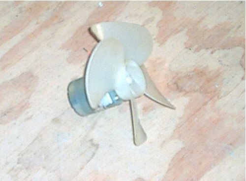
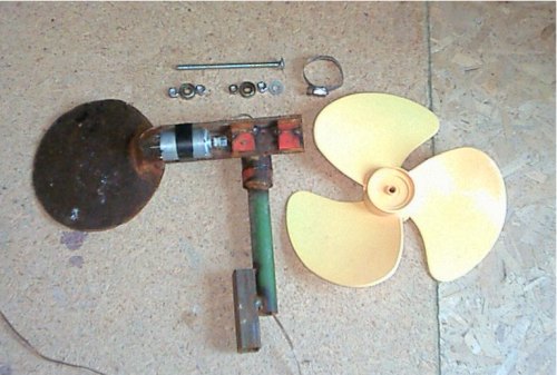
After much tinkering, I came up with this. It's a 5/16" threaded carriage bolt stuck through the blade. The carriage head bites into the plastic blade, then there is the roller blade bearing, another bearing, then a nut on the end of the bolt which the nylon pulley already on the motor is "screwed" into. All this is placed inside an angle iron, with strap iron "shims" to hold the bearings. Some might notice I don't have the motor end bearing clamped. Yep. That's because I welded the swivel pipe on the wrong side of my mark. Now there's no room for a clamp. And in this photo, I just have the motor taped on. A hose clamp was added later.
The Tail Fin is a 6 inch circle. It's a piece of scrap iron. It's pretty light, around 14 gauge, and it's not quite enough surface area. However, if my pivot pipe was welded in the correct place, the tail would have more leverage, and it might be enough. As is, the machine actually turns out of the wind a bit as the wind increases. Not a bad thing at all.
The "frame" is an 8" long piece of 1/8" thick, 1 1/2" sides angle iron.
The center of the pivot pipe should be 1 3/4" from the propellor end of the angle iron.
The "shims" under the bearings are made from 1" square by 1/4" inch thick strap iron, and "spot" welded in place. There are 4 of them. 2 are placed under each bearing to form a "corner." (Not quite sure of a good way to word that....) Or, one shim is horizontal, (on top of the bearing) and one shim is vertical (behind the bearing).
The fan blade is 11" in diameter, and has 3 blades.
To "screw" the nylon motor pulley into the nut, I put a two nuts on the end of the carriage bolt, after the bearings and prop were put on, then set it in the angle iron. The last nut was only half way on, and the second nut kept it form spinning. Then I gripped the pulley with vise-grips, and turned the blade. It screwed itself into the nut quite easy. It seems to be holding, even without glue. I had planned on taking it apart and super gluing it, but it's holding so far.
And the run through of the carriage bolt-- It's a 6" by 5/16" carriage bolt, with threads all the way to the head. I drilled out the blade with a 5/16" bit, since it had a single drive flat. (Not a round hole) Then I put the bolt in, then a washer, nut, bearing, nut, space, nut bearing, nut, nut and nylon pulley.
When you put on the hose clamps, put the screw part of them on the bearing. That part of the hose clamp is curved a bit, and it seems to hold that way better than having the screw on the flat of the angle iron.
The pivot pipe is 2 inches of 1" ID pipe. It fits over a piece of 3/4" pipe. I cut a small "washer" of 1" pipe and spot welded it over the 3/4" pipe to act as a "bearing." The wind generator simply slides over the 3/4" pipe and rests on the "washer." A little grease helps it rotate freely. Then the wire is run down the pipe to the diode and batteries. With the wire running down the center of the pipe, the machine doesn't need a "slip ring." The picture below shows this concept a bit better.
The most I've seen from this machine is half an amp at 1.8 volts. The solar light actually turns on the LED once voltage reaches 1.8 volts, and so far, it doesn't seem to over charge the cells. These solar lights just "pop" apart, so I did such, and soldered a couple feet of wire on to the battery wires. This runs out to a dual "AA" battery holder, hidden under the porch. The batteries are wired in parallel. Then I soldered a diode on, and attached the wires going up to the wind generator. The battery holder in the Solar light is NOT used anymore.
Anything I missed? My e-mail is on my home page. Feel free to e-mail me and ask questions. But make sure you READ this page first. I probably won't respond if the answer is already here.
return HOME return to Contraptions