| Command Logic Light Kit |
| This diagram above is what we all are paying 7 dollars for at your local RS to have lights on your XMods. However you can make it yourself for about 4 dollars and get the LED's you want. If you wish to use a higher rated LED you can, but remember the limitation of the batteries and Main PCB. On the far right are the respective color coded wires to the Main PCB underneath the plastic connector. The yellow wire is the common ground wire for Q1 and Q2. The Orange wire is the common ground for D1 - D4. Mean while C1, and C2 filter out RF signals so it doesn't feed back into the Main PCB. The Red |
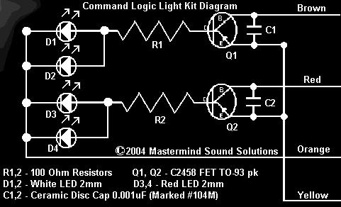 |
| and Brown wires provides the base signals (in this case a voltage change) to turn the circuit on. Q1 is on when that car is going forward or in reverse. Q2 turns on after the car has been going forward for a bit then followed by a hard reverse (which is that brake mode) which in turns charges the cap on the Main PCB while the cap on the motor is also charged causing the motor to lock up and sending a voltage spike to the red wire. It is a pretty basic switching circuit. Also take note that it can also be replicated with general purpose transistors but the switching will be slower then with these FETs. |