 |
|
|
|
|
|
|
|
|
|
|
|
|
|
|
|
|
|
|
|
|
|
|
|
|
|
MARK III UPDATES |
|
|
|
JULY 22 |
|
|
|
Big update. In the last two weeks, the Mark III has undergone a rather radical redesign process. My original mount for the gun was a cradle of solid wood that the pipe would sit down in. That's gone out the window. I've just finished making a mounting rail out of a 1.5" wide strip of 2.5" pvc. 2" pipe sits on it perfectly and it screws down on top of a 2x4. It's pretty slick if I do say so myself because it will greatly simplify the adjustment of the gas sleeve. I think I mentioned that I have no idea just how far down the barrel my gas ports need to be, but with this rail system, I'll be able to adjust back and forth with the greatest of ease.
The change meant having to rebuild the gas sleeve, but that's almost done now. It also means that I'll be able to use 2.5" for the actual reciever. This will greatly simplify things because it will align the shells perfectly once they drop into place. |
|
|
|
MAY 1 |
|
|
|
EXTRACTOR |
|
|
|
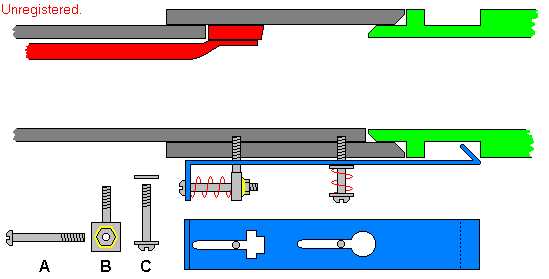
It's taken me a couple months, but I finally figured out how to pull spent shells out of the breach. I first had the notion to make the claw out of one peice of spring steel, but heat treating that would require a forge, which I haven't built yet. Anyway, I thought this design up in class one day. No special materials will be needed. |
|
|
|
 |
|
|
|
This is a top view of the bolt. The extractor claw is shown in blue. It is attached to the bolt by machine screws B and C. Screw B has a threaded nut attached to it, which holds Screw A. As a shell (green) is pulled to the left (out of the breach), the extractor slides to the right. The spring around Screw A compresses and absorbs some of the impact.
The spring on Screw C keeps the extractor pressed against the shells. A flat washer sits between the spring and the extractor.
To remove the extractor, Screw A is removed, and the extractor is slided back (to the left). This lines up the large holes in the extractor with the screws and the extractor can be pulled off. |
|
|
|
GAS METER |
|
|
|
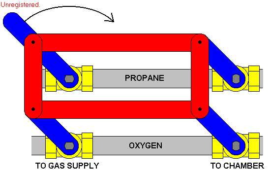
This is a tandem setup of two volumetric gas meters. Each meter uses two ball valves, all of which are operated by one handle. This design came from the hight adjustment mechanism of an old typewriter table. |
|
|
|
 |
|
|
|
The picture shows the meter in firing position. Note that the valves on the left side are open while the valves on the right are closed. In this position, the meters are charged by the gas sources. When the lever is thrown to the right, the gas sources are shut off, and the meters open to the chamber. When the handle is returned to firing position, it is recharged. |
|
|
|
MAIN PAGE |
|