Series of photographs of prototype Malawi Cart
|
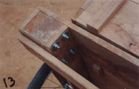
13. Detail view of a front corner of the prototype cart as seen from below and inside of the chassis. (Note that the chassis itself has no front or rear, it is symmetrical.) Notice the four bolts connecting the ends of the wheel-frames together. We found that these long (6 1/2"/16cm)bolts were unavailable in most shops in Malawi, and so, in the production models of the cart, ordinary bicycle rear axles were used as bolts. These rear axles are 6 1/2"/16cm long and cost K15 (~15 US $0.30). They are cheaper than any comparable ordinary bolt, and, more importantly, are universally available. If you refer to photograph 9, you will observe that the ends of the frames are affixed with two of these 6 1/2"/16cm axle-bolts, and four large (4"/10cm) wood screws. Note also the wooden toggle which clamps the upper box body to the chassis. There are four of these toggles, each of which pivots on a wood screw driven into the underside of the body. They are only lightly stressed. |
|
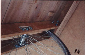
14. Detail view of the underside of the cart, showing details of the wheel mounting system. There is a metal plate bolted to the inside of each of the four vertical frame members. One is visible in the photo. This plate has three holes drilled through it, and performs two separate functions. It acts as a washer, preventing the pressure of the hub's cone from pressing into the wood frame. At either end, it is bolted through by a bolt to the wooden frame. These two bolts transfer some of the load (compressive force) from the frame to the axle, via the steel plate. They thus reduce the compressive force acting on the wood pressing on the axle, and reduce any wear that might occur at that joint. This design element may not be necessary when hardwood is used for the frames. It may be important when softer wood is employed. On the outside of each frame member is another steel plate. It is not a structural element, but merely a retaining plate, preventing the axle nut and the nuts on the two auxiliary bolts from coming loose. Notches cut in these retaining plates engage with the three nuts, preventing them from turning. The plate itself is fastened to the wooden beam with two small wood screws. |
|
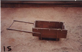
15.The cart body. Note that the side cleats are clench-nailed to the side planks for strength. The side cleats are also extended below the floor for three reasons. Although the rear ends of the body side planks are rigidly affixed to the side planks by the screwed and nailed box joints, the front ends of these side planks are essentially unsupported, as the front is merely located between two sets of cleats, and is free to slide up and out. The extended cleats, especially the front cleats, transmit any outward movement of the sides to the frames, and this prevent the front of the side panels from flopping open. Additionally, these extensions serve to correctly locate the body when affixing it to the sub frame, and have beveled ends to make this job easier. Finally, the legs keep the body of the ground when it is not in use. The cart is not painted, and ideally should be treated with "Solignum" or some other brand of penetrating wood preservative to extend its life. Note the holes bored in the upper planks for fastening ropes when necessary. The two handles are connected by a cross piece. The operator may either push or pull the cart. Pulling is more comfortable when somewhat longer handles than those depicted are employed, with the operator standing inside the shafts, between the cart and cross-bar, pushing against the latter. It remains to be seen as to which propulsion method, and therefore which handle length, will prove more popular. Note that these photos were taken of the prototype cart (completed July 10, 2000) which was constructed with unseasoned wood, and therefore shows shrinkage spaces between the planks. |